The ABIG CHR 2/650 is a braking chopper designed to regulate DC-link voltage in variable frequency drive (VFD) systems and other power electronic applications. During motor deceleration, induction motors operate as generators and return energy to the DC link, which can cause overvoltage faults if not controlled. The ABIG CHR 2/650 monitors the DC-bus voltage and activates an external braking resistor to dissipate excess energy as heat. This provides reliable DC-link voltage control, prevents drive system trips, and protects sensitive power electronic components while ensuring continuous operation.
The ABIG CHR 2/650 platform can be scaled to meet various power system requirements. Up to seven modules can be connected in parallel, providing a peak braking power of approximately 1250 kW.
- Industrial Automation: Manages regenerative energy in cranes, hoists, elevators, conveyors, centrifuges, and other dynamic drive systems.
- Battery Energy Storage Systems (BESS): Provides overvoltage protection during charging and testing cycles, preventing excessive battery voltage.
- Marine Power Systems: Provides additional protection when onboard grids or generators cannot absorb regenerative energy.
- DC Infrastructure: Maintains DC-link voltage stability in microgrids and renewable energy systems requiring fast dynamic response.
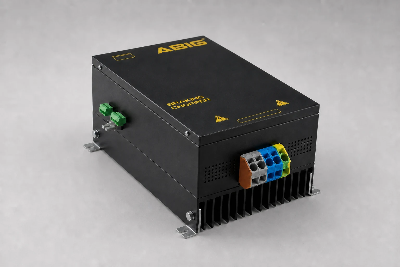
- Broad Compatibility: Suitable for three-phase motor drives and various DC power systems.
- High Power Scalability: Up to seven modules can operate in parallel, providing approximately 1250 kW peak braking power.
- Operating Range: Compatible with DC-link voltages from 200 VDC to 1000 VDC.
- Integrated Protection: Monitors and protects against overvoltage (OV), overtemperature (OT), short-circuit (SC), and resistor thermal (RT) faults.
- Compact Industrial Design: Wall-mounted construction with maintenance-free operation.
- Customization: Supports application-specific firmware and hardware modifications.
- Status Indication: LED indicators for operating status and fault conditions (RUN, OV, OT, SC, RT).
- Input Voltage Range
200–1000 VDC
- Brake Voltage Threshold
250–850 VDC *
- Peak Braking Power
178.5kW
@ 10% duty cycle
- Peak Braking Current
210A
@ 10% duty cycle
- Rated Continuous Power
34kW
- Rated Continuous Current
40A
- Minimum Resistance Value
3.1Ω
@660 V DC
- Ambient Temperature
−10 … 40 °C
- Altitude (without derating)
≤2000m
- Dimensions (W × H × D)
209.2 mm × 293.4 mm × 146.9 mm
- Weight
4kg
- Protection Degree
IP20
Per EN 60529
- Parallel Operation
≤7modules
Approximately 1250 kW peak braking power @ 10% duty cycle
* The brake voltage threshold is factory-set within the specified range according to customer requirements.
** For custom requirements or specifications beyond these values, please contact Hilkar.