Motor drives control the speed of three-phase squirrel-cage induction motors and three-phase synchronous motors by varying the output frequency while maintaining the required voltage-to-frequency ratio.
During deceleration or when the motor operates as a generator (i.e., above synchronous speed), regenerative energy is fed back into the drive, causing the DC bus voltage to rise. To protect the drive and connected equipment, the DC bus voltage must be maintained below its permissible limit.
Although regenerative energy can be fed back into the power grid, this solution often requires additional power electronics and control equipment, making it uneconomical for many applications. A more practical and cost-effective solution is to use a brake chopper together with a braking resistor, which safely dissipates the excess energy as heat. Hilkar's braking resistors provide a compact, reliable, and economical solution for dynamic braking applications. Designed to accommodate a wide range of duty cycles, they are available in power ratings ranging from a few watts to several megawatts.
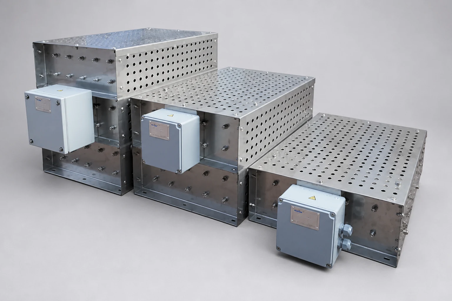
- Designed and manufactured for any power rating and duty cycle.
- Enclosures available in hot-dip galvanized steel, stainless steel, or aluminum
- Standard and custom-engineered designs to meet specific application requirements
- Compatible with all major Variable Frequency Drive (VFD) brands and models
Fan-cooled braking resistors available for high continuous-duty applications and space-constrained installations, particularly in the marine, mining, and traction industries
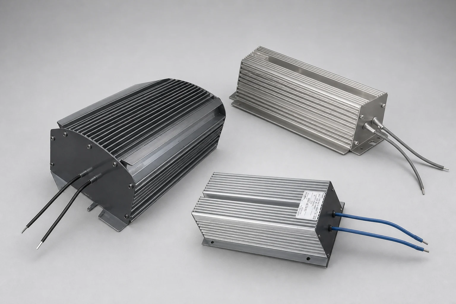
- Aluminum heat-sink enclosure
- Hot-dip galvanized steel enclosure
- Stainless-steel enclosure
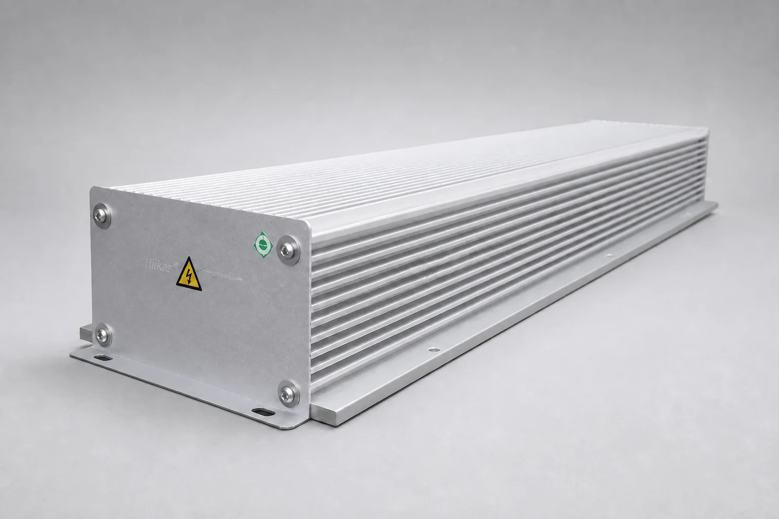
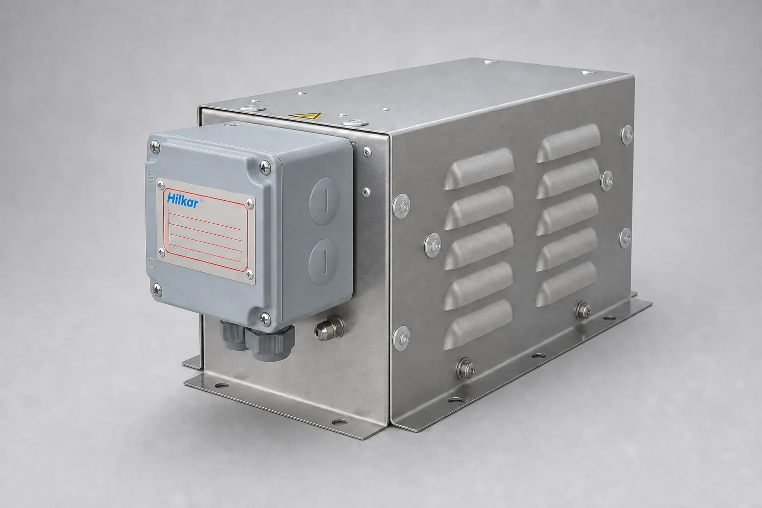
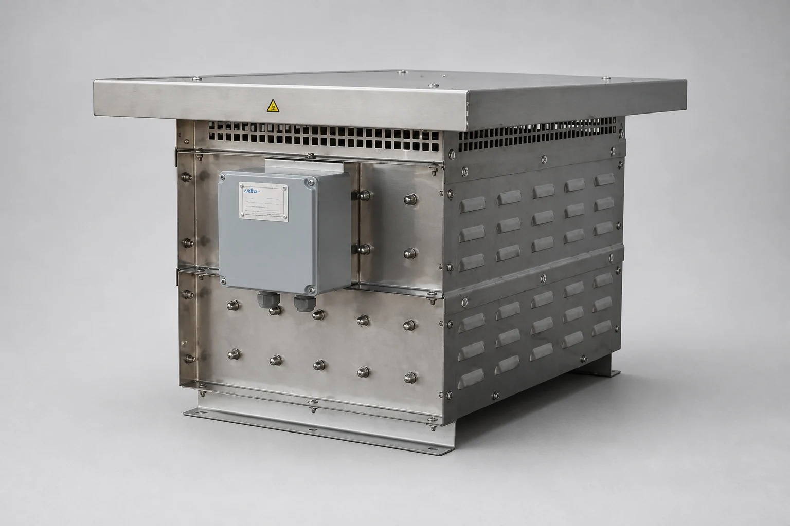
- Continuous Power Rating: From a few watts to several megawatts
- Cooling Method: Natural convection or forced-air cooling
- Protection Degree: IP20 (other protection degrees available upon request)
The resistance value of the braking resistor must not be lower than the minimum value specified by the VFD manufacturer. Selecting a lower resistance may result in excessive braking current and damage to the VFD or braking chopper. Conversely, selecting a significantly higher resistance reduces the braking current and increases the braking time. The actual braking time depends on the inertia and speed of the rotating system.
If the required braking time is unknown or approaches the total operating cycle time, it is recommended to select a braking resistor with a continuous power rating equal to or greater than the motor's rated power to provide an adequate safety margin.
The graph below illustrates the relationship between the Overload Multiplier, Overload Time, and Cooling Time.
Cooling Times
- Tc = 30 minutes
- Tc = 1 minute
- Tc = 15 seconds
- Rbr
- Braking resistor
- Q
- Braking chopper (IGBT)
- C
- DC link capacitor
- M 3~
- Three-phase motor
Nominal braking power