Load banks apply controlled electrical loads to power sources. Resistive elements convert active power into heat, while inductive and capacitive elements exchange reactive power with the source.
Unlike variable field loads, load banks provide predetermined and adjustable loading conditions, enabling reliable testing, commissioning, and performance verification of electrical power systems.
A resistive load bank provides an electrical load equivalent to the generator output and applies an equal mechanical load to the prime mover. This enables accurate performance testing of generator systems under controlled conditions.
Hilkar R-Series resistive load banks are available in portable and stationary configurations, with load steps as low as 1 kW for precise active load control.
Designed for demanding industrial environments, R-Series load banks feature a rugged construction with vibration-resistant stainless steel resistors and integrated control and switching systems. They can be operated through local, remote, wireless remote, or automatic control systems.
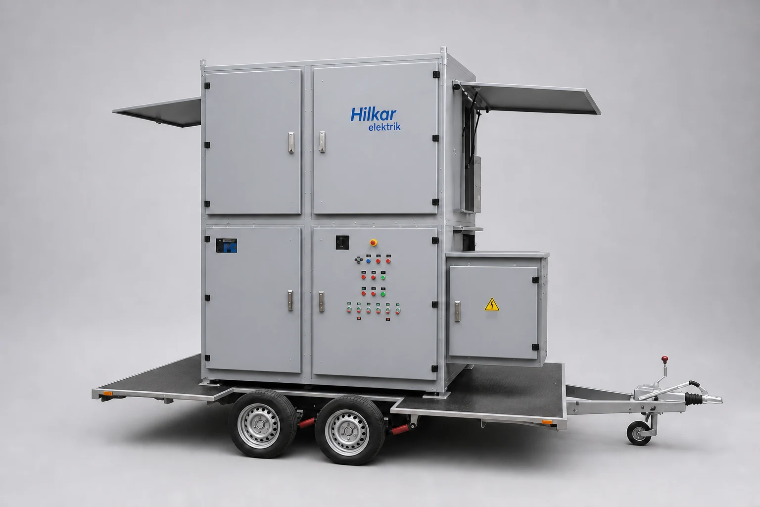
Suitable for both workshop and field testing, R-Series load banks can also be supplied as trailer-mounted units for flexible on-site operation.
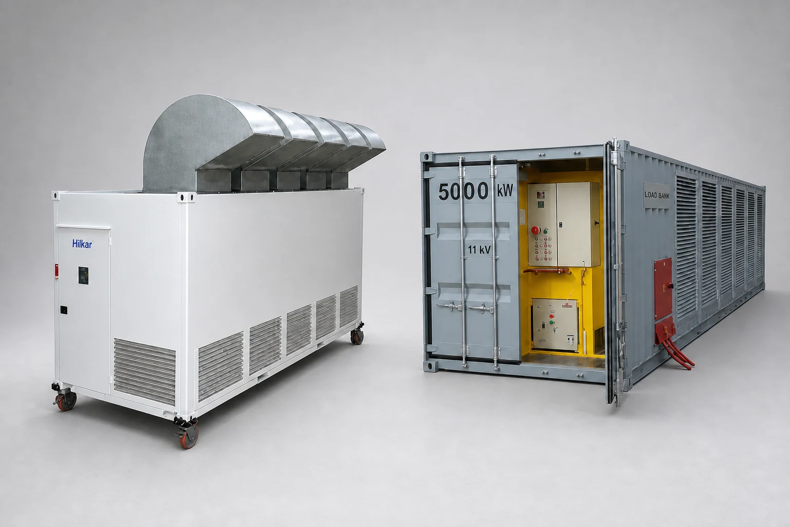
- Robust and durable design
- Configurable load combinations: R / L / C / RL / RC / RLC
- Vertical or horizontal air discharge configuration
- ISO containerized or custom enclosure options
- Integrated remote control system with data acquisition, monitoring, and load step control
- Easy integration and synchronization with other load banks
- Corrosion-resistant coating for outdoor applications
- Vibration-resistant stainless steel resistors
- Designs compatible with IEC 62116, IEEE Std 929, and UL 1741 standards
Hilkar load banks can be equipped with optional touchscreen LCD displays, wireless remote load step controllers, and PC-based control software for advanced testing and monitoring. The control system provides fan start/stop control, electrical parameter monitoring, load step management, timing functions, data recording, test modes, and fault detection. PC controllers communicate with the load bank via a USB connection.
Load banks include circuit breaker protection and provide easy access to switchgear compartments and load elements. Integrated safety functions protect against fan failure, low airflow, overvoltage, overheating, and phase sequence faults. Suitable for flexible field operation, trailer-mounted R-Series resistive load banks provide reliable solutions for on-site generator testing.
| Auxiliary Voltage | 400 V, 50–60 Hz (other voltages and frequencies available upon request) |
|---|---|
| Control | Manual control (local and/or remote) or automatic control via DSP controller |
| Portability | Forklift channels, lifting lugs, and wheels for easy transportation |
| Model | Cooling System | Load Step Resolution | Designed Voltage | Capacity (kW) | Dimensions (W × L × H) cm / in | Weight (kg/lb) |
|---|---|---|---|---|---|---|
| LB.RH.1 | Horizontal Forced Air | min. 1 kW | up to 690 V 50–60 Hz or DC | 0–50 | 65 × 100 × 65 / 25.6 × 39.4 × 25.6 | 100–150 / 220–331 |
| LB.RV.1 | Vertical Forced Air | min. 1 kW | up to 690 V 50–60 Hz or DC | 0–50 | 65 × 65 × 175 / 25.6 × 25.6 × 68.9 | 150–200 / 331–441 |
| LB.RH.2 | Horizontal Forced Air | min. 5 kW | up to 690 V 50–60 Hz or DC | 50–250 | 85 × 125 × 85 / 33.5 × 49.2 × 33.5 | 200–250 / 441–551 |
| LB.RV.2 | Vertical Forced Air | min. 5 kW | up to 690 V 50–60 Hz or DC | 50–250 | 85 × 125 × 85 / 33.5 × 49.2 × 33.5 | 200–250 / 441–551 |
| LB.RH.3 | Horizontal Forced Air | min. 5 kW | up to 690 V 50–60 Hz or DC | 250–400 | 100 × 150 × 100 / 39.4 × 59.1 × 39.4 | 250–400 / 551–882 |
| LB.RV.3 | Vertical Forced Air | min. 5 kW | up to 690 V 50–60 Hz or DC | 250–400 | 100 × 100 × 200 / 39.4 × 39.4 × 78.7 | 400–500 / 882–1102 |
| LB.RH.4 | Horizontal Forced Air | min. 5 kW | up to 690 V 50–60 Hz or DC | 400–750 (@400 V: max. 500 kW) (@690 V: max. 750 kW) | 125 × 175 × 125 / 49.2 × 68.9 × 49.2 | 500–650 / 1102–1433 |
| LB.RV.4 | Vertical Forced Air | min. 5 kW | up to 690 V 50–60 Hz or DC | 400–750 | 125 × 125 × 225 / 49.2 × 49.2 × 88.6 | 600–700 / 1323–1543 |
| LB.RH.5 | Horizontal Forced Air | min. 5 kW | up to 690 V 50–60 Hz or DC | 750–1000 | 150 × 200 × 150 / 59.1 × 78.7 × 59.1 | 800–1000 / 1764–2205 |
| LB.RV.5 | Vertical Forced Air | min. 5 kW | up to 690 V 50–60 Hz or DC | 750–1000 | 150 × 150 × 250 / 59.1 × 59.1 × 98.4 | 900–1000 / 1984–2205 |
| LB.RH.C10 | Horizontal Forced Air | min. 25 kW | up to 690 V 50–60 Hz or DC | 1000–2000 | 210 × 300 × 220 / 82.7 × 118.1 × 86.6 | Variable as per load steps |
| LB.RV.C10 | Vertical Forced Air | min. 25 kW | up to 690 V 50–60 Hz or DC | 1000–2000 | 210 × 300 × 220 / 82.7 × 118.1 × 86.6 | Variable as per load steps |
| LB.RH.C20 | Horizontal Forced Air | min. 25 kW | up to 36 kV 50–60 Hz or DC | 1000–6000 (@0.4 kV: max. 6000 kW) (@4.16 kV: max. 3000 kW) (@36 kV: max. 1000 kW) | Standard 20-foot high-cube container dimensions | Variable as per load steps |
| LB.RV.C20 | Vertical Forced Air | min. 25 kW | up to 36 kV 50–60 Hz or DC | 1000–6000 (@0.4 kV: max. 6000 kW) (@4.16 kV: max. 3000 kW) (@36 kV: max. 1000 kW) | Standard 20-foot high-cube container dimensions | Variable as per load steps |
| LB.RH.C40 | Horizontal Forced Air | min. 25 kW | up to 36 kV 50–60 Hz or DC | 3000–10000 (@0.4 kV: max. 10000 kW) (@4.16 kV: max. 6000 kW) (@36 kV: max. 3000 kW) | Standard 40-foot high-cube container dimensions | Variable as per load steps |
| LB.RV.C40 | Vertical Forced Air | min. 25 kW | up to 36 kV 50–60 Hz or DC | 3000–10000 (@0.4 kV: max. 10000 kW) (@4.16 kV: max. 6000 kW) (@36 kV: max. 3000 kW) | Standard 40-foot high-cube container dimensions | Variable as per load steps |
Hilkar load banks can be operated through various control options to meet different testing requirements:
Local Control
Remote Control
Wireless Remote Control
Automatic Control
- Frequency
DC or 50 / 60 / 400 Hz
- Load Type
Resistive
≤ 36 kV
- Measurements
V, A, W, VAr, Hz, cosφ
- Applied Voltage and Frequency (System voltage and operating frequency)
- Installation Type (Mobile or stationary)
- Load Step Resolution
- Service Location (Indoor or outdoor application)
- Required Load Capacity (kW)
- Blower and Control Voltage (Auxiliary supply voltage requirements)
- Control Power Supply (Internal and/or external )
- Meters (Voltmeter, Ammeter, kW meter, kVA meter, cosφ, frequency meter)
- Optional Communication Interface RS-232 / RS-485 computer interface (wireless interface available upon request)
- Automatic Controller Required / not required
- Wireless Remote Control Required / not required
- Protection Degree IP20 (indoor), IP20 (outdoor under roof), IP55 (outdoor)