Hilkar Primary Current Injection Testers are designed for testing protective relays, circuit breakers, and current transformers (CTs) using high, adjustable test currents.
By injecting controlled current into the primary circuit, the system response can be evaluated at specific current levels, including relay trip operation and trip time verification.
The testers support independent phase loading, allowing flexible simulation of various fault and operating conditions for accurate protection system testing.
- CT turns ratio testing
- CT polarity testing
- Protective relay trip time testing
- Circuit breaker trip testing
- CT magnetization curve plotting
- CT burden testing
- Busbar resistance measurement
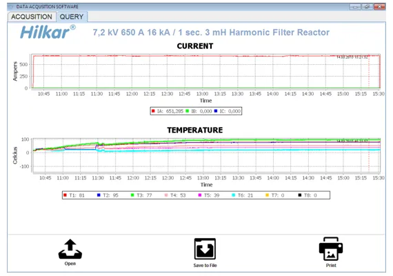
- Temperature rise testing
- Q1, Q2
- Circuit breakers under test (closed)
- a, b, c, n
- Tester outputs (phases and neutral)
For proper operation of the Primary Current Injection Tester, follow these guidelines: Set the position switch to the appropriate test configuration (e.g., 3 × 2.5 V / 4000 A or 3 × 400 V / 45 A) according to the required test current. Use intermediate connection cables with equal cross-sections and equal lengths, maintaining a minimum current density of 2 A/mm².
Arrange the insulated outgoing and return current cables close together to minimize loop inductance and voltage drop. Use the cable arrangement, insulation, and mechanical restraint specified for the test current and duration.
Operate the unit only using the ON/OFF switch located on the external control box. These practices ensure maximum current output, stable operation, and accurate test results.
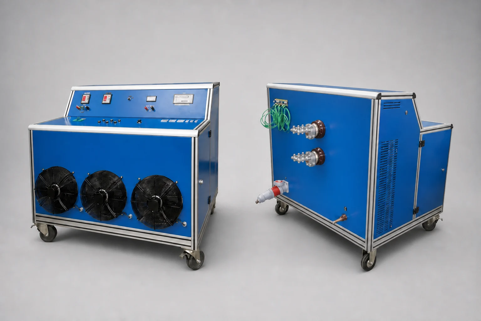
| Parameter | AK23 (3 × 30 kVA) | AK43 (3 × 60 kVA) | AK63 (3 × 120 kVA) |
|---|---|---|---|
| Input | 3 × 400 V / 130 A | 3 × 400 V / 260 A | 3 × 400 V / 520 A |
| First Output | 3 × (0–400) V / 0–130 A AC | 3 × (0–400) V / 0–260 A AC | 3 × (0–400) V / 0–520 A AC |
| Second Output | 3 × (0–15) V / 3 × (0–2000) A AC | 3 × (0–15) V / 3 × (0–4000) A AC | 3 × (0–20) V / 3 × (0–6000) A AC |
| Weight (kg) | 500 | 640 + 100 | 700 + 100 |
| Dimensions (W × H × D), mm | 700 × 1000 × 1600 | 700 × 1000 × 1600 | 1000 × 2000 × 1200 |
| Ammeters | 3 × (0–2.00) kA | 3 × (0–4.00) kA | 3 × (0–6.00) kA |
| Cooling Method | Fan cooling | Water cooling (22 °C) | Water cooling (22 °C) |
- Transport
Wheeled design
- Temperature Measurement
≤400°C
Type K thermocouple, 8 probes, 4 m cable length
- Computer Interface (Optional)
RS-232 / RS-485
Wireless interface available upon request
- Data Logger (Optional)
Supports ≤ 32 temperature probes