Railway power resistors are used in traction systems to safely dissipate excess electrical energy during dynamic braking. They protect traction converters from overvoltages, reduce mechanical brake wear, and ensure reliable braking performance under demanding operating conditions.
Railway applications require power resistors capable of withstanding severe electrical, thermal, mechanical, and environmental stresses. They are designed and tested in accordance with applicable railway standards, including IEC 60322, which specifies the design and testing requirements for open-construction power resistors used in rolling stock. Additional railway standards address vibration, shock, and insulation coordination to ensure reliable long-term operation.
The design of a railway power resistor depends on the vehicle type, propulsion system, braking duty, installation location, and cooling method. Because each rail vehicle is designed for specific propulsion power, passenger or freight capacity, and operating conditions, resistor solutions are custom-engineered for each application.
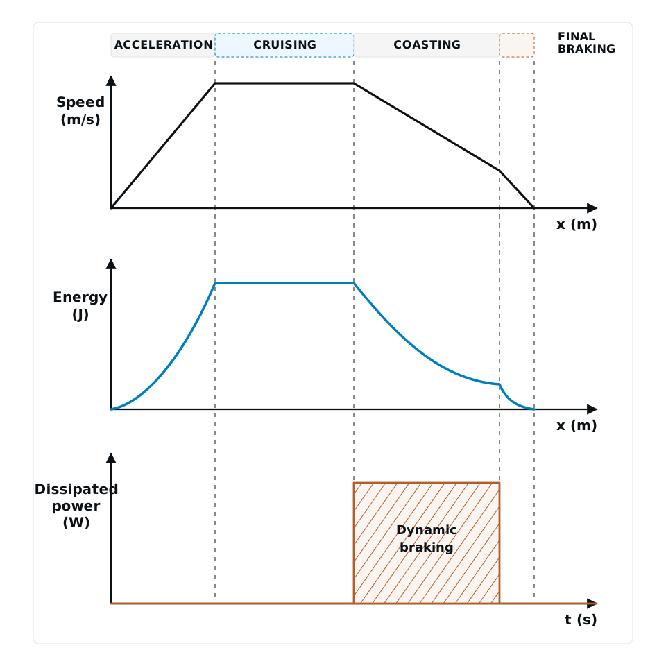
Most modern electric rail vehicles use regenerative braking systems capable of returning braking energy to the catenary. However, in many metro and tramway networks, the DC traction supply is unable to absorb regenerative energy. Under these conditions, braking resistors safely dissipate the excess energy as heat, maintaining effective braking performance and protecting the traction equipment.
In mainline railway applications, where bi-directional energy exchange with the grid is often available, braking resistors are primarily used in diesel-electric locomotives and in electric locomotives operating on networks that cannot absorb regenerative braking energy.
- IEC 60322 : 2001 — Railway applications. Electric equipment for rolling stock. Rules for power resistors of open construction.
- IEC 61373 : 2010 — Railway applications. Rolling stock equipment. Shock and vibration tests.
- EN 50124-1 : 2001 — Railway applications. Insulation coordination. Basic requirements. Clearances and creepage distances for all electrical and electronic equipment.
Public transport vehicles such as metros, light rail, and tramways operate under frequent acceleration and braking cycles between stations. During acceleration, energy flows from the catenary to the traction motors; during braking, the traction motors operate as generators, converting kinetic energy into electrical energy.
Where regenerative energy cannot be returned to the catenary, braking resistors safely dissipate the excess energy as heat. This ensures reliable braking performance, protects the traction converter from overvoltage, and significantly reduces the wear of mechanical braking systems.
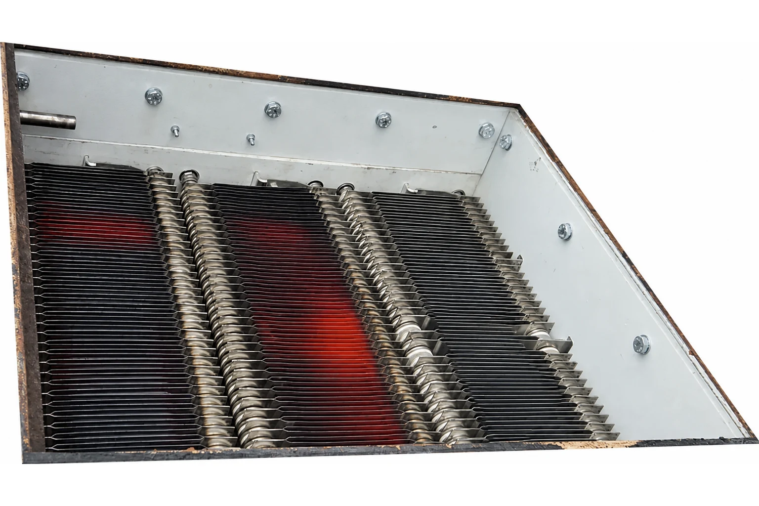
Braking resistors are designed according to the required braking power, duty cycle, insulation requirements, mounting location, and cooling method. They can be roof-mounted, underfloor-mounted, or installed in dedicated equipment compartments, and are available with natural or forced-air cooling.
Features of Railway Braking Resistors
- Minimal resistance variation over the operating temperature range
- Robust mechanical construction for high shock and vibration resistance
- Long service life under repeated thermal cycling
- High thermal capacity for frequent braking cycles
- Natural or forced-air cooling options
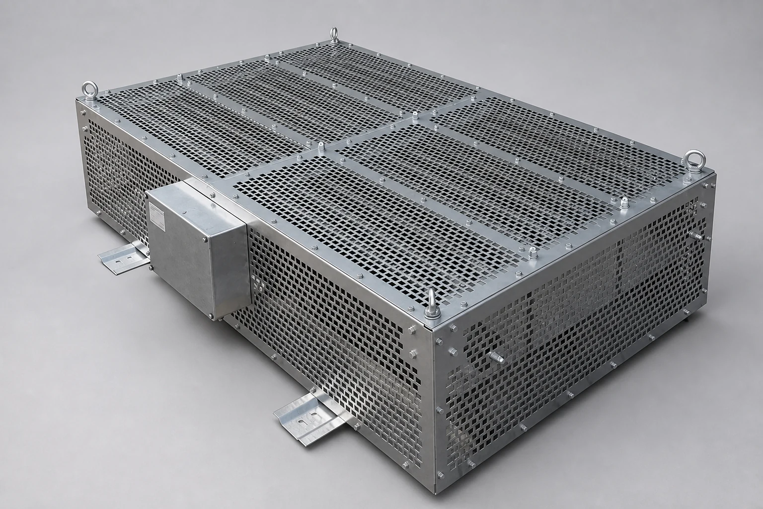
Heavy rail vehicles typically operate under prolonged braking conditions, particularly on steep gradients where freight locomotives transport heavy loads over long distances. Unlike urban transit applications, braking in heavy rail systems often involves sustained high-power energy dissipation.
Braking resistors play a critical role in reducing mechanical brake wear and maintaining reliable braking performance during extended operating periods. They are designed with robust mechanical structures, high thermal capacity, and stable electrical characteristics to withstand elevated temperatures and demanding railway environments.
To maintain consistent braking performance as the resistor temperature increases, the resistance variation must remain minimal over the entire operating temperature range.
Features of Power Resistors Used in Heavy Rail Vehicles
- Minimal resistance variation over the operating temperature range
- Continuous operation at elevated temperatures
- Robust mechanical construction for high shock and vibration resistance
- High thermal capacity for prolonged braking cycles
- Long service life under severe operating conditions
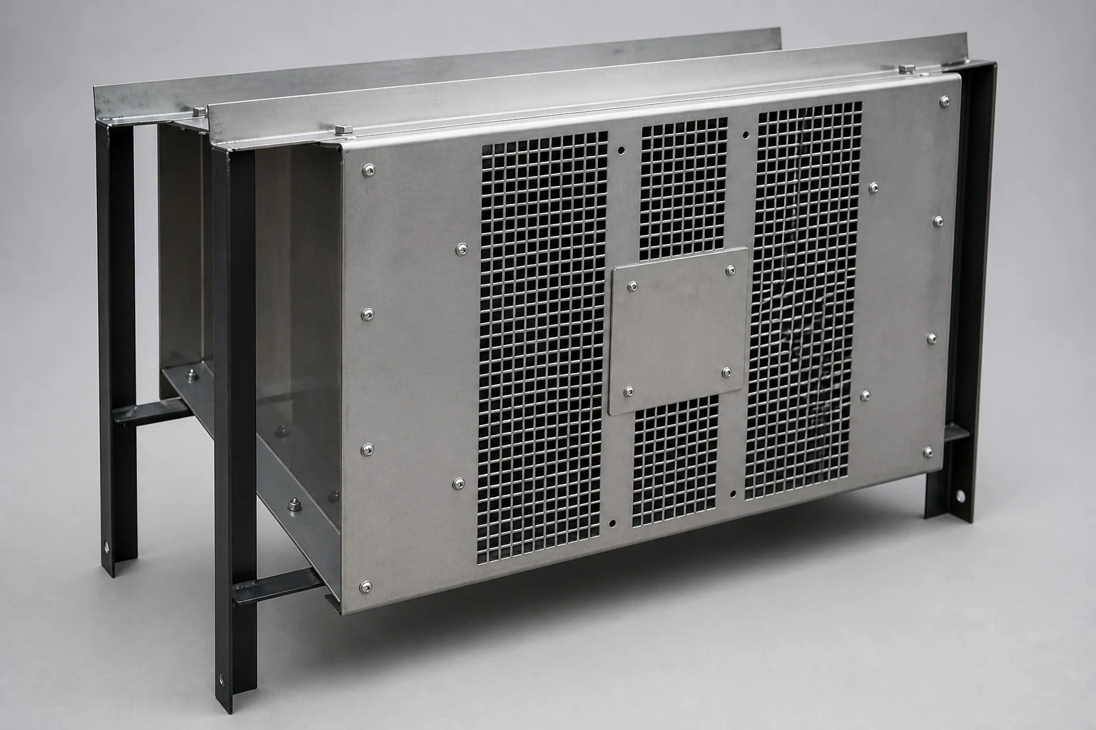
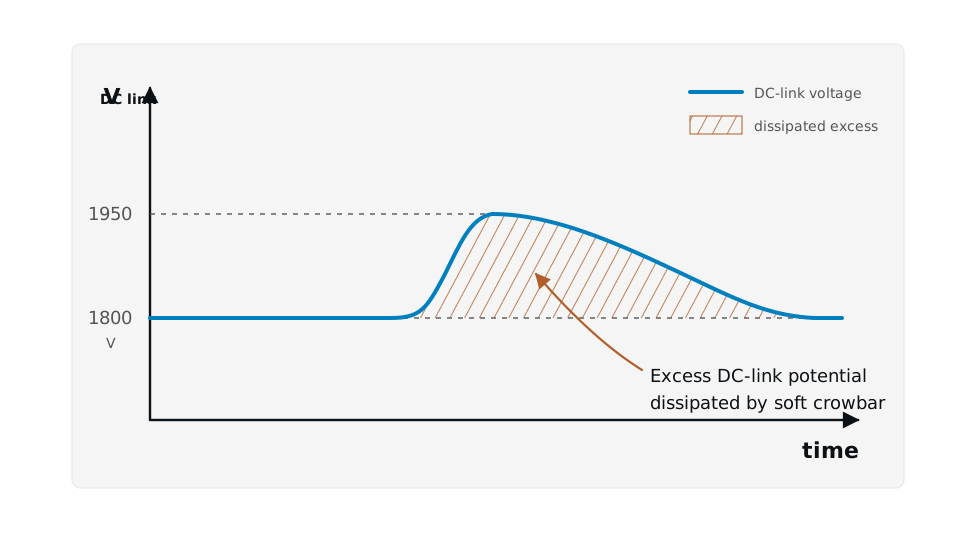
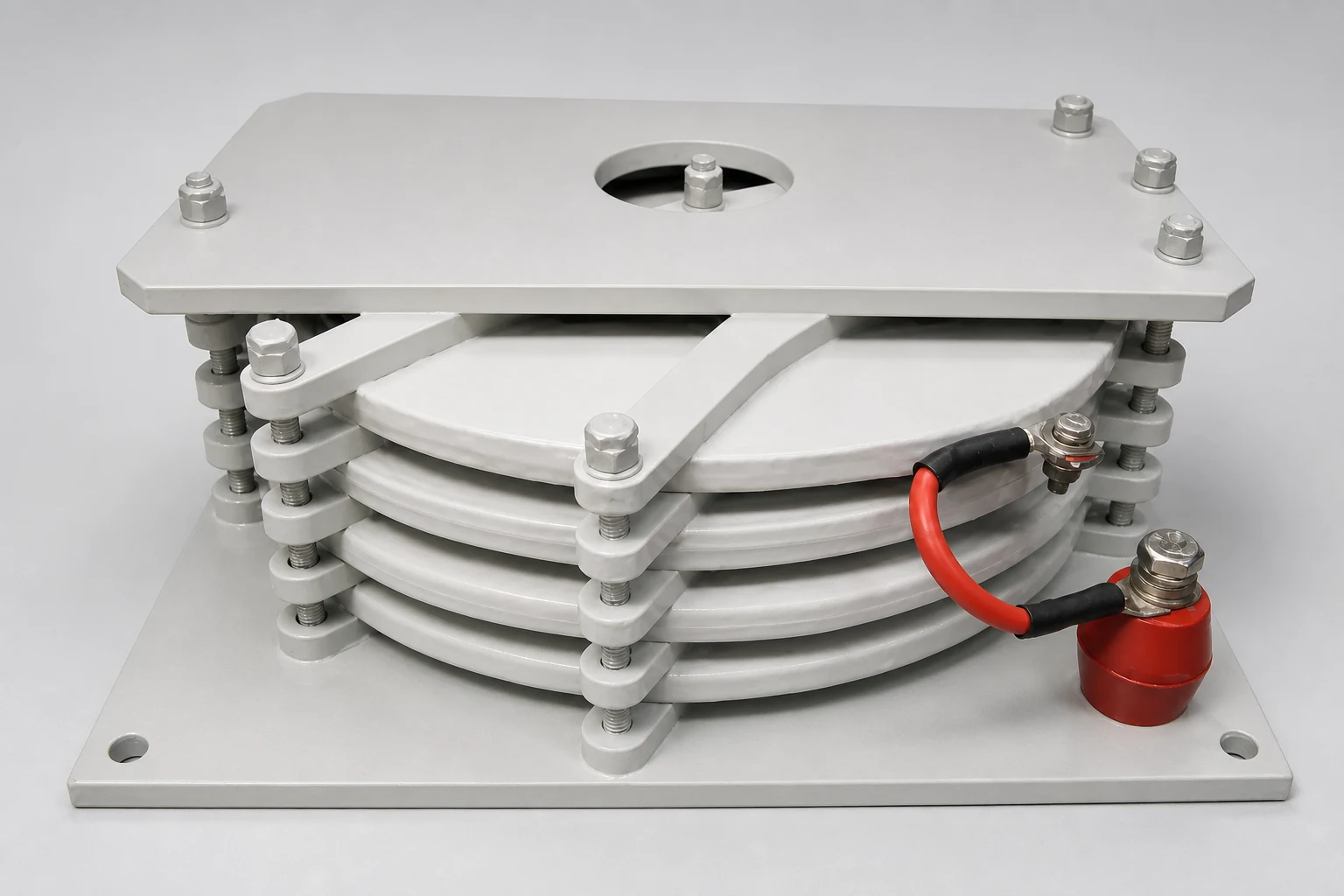
Crowbar resistors protect traction converter power electronics from excessive overvoltage and overcurrent conditions during transient events, such as grid disturbances and faults. Crowbar protection systems are generally classified into two types:
Soft Crowbar
A soft crowbar limits DC-link overvoltage by connecting a resistor to the DC link through an IGBT. It dissipates the excess energy and reduces the voltage stress on the converter components.
Hard Crowbar
A hard crowbar provides rapid protection by connecting a resistor to the DC link through a thyristor, triggering the high-speed circuit breaker (HSCB) to isolate and protect the converter system from overvoltage damage.
Crowbar resistors are designed to withstand very high energy pulses over short durations. Their electrical ratings are determined based on the converter topology, front-end converter ratings, HSCB characteristics, and the energy stored in the DC-link capacitors.
Features of Crowbar Resistors Used in Traction Converters
- Compact mechanical design
- High resistance to sudden thermal variations
- Robust construction for shock and vibration resistance
- Minimal resistance variation during high-temperature operation
- High pulse energy absorption capability
- HSCB
- High-speed circuit breaker
Wagon heating resistors are used either as part of regenerative braking systems or as standalone heating units in railway passenger vehicles. In addition to providing heating functions, they incorporate protection and diagnostic features to ensure safe and reliable operation.
Protection Functions
- Overtemperature protection for heating elements
- Protection against excessive wagon temperature
- Fan failure protection
- Sensor power supply fault protection
- Redundant circuit breaker protection in case of contactor failure
- Transmission of heater operating status (ON/OFF) signals to the train control system
Hilkar wagon heating resistors are designed and manufactured in accordance with IEC 60322 railway resistor requirements. Internal electrical and electronic sub-components comply with EN 50155 railway standards.
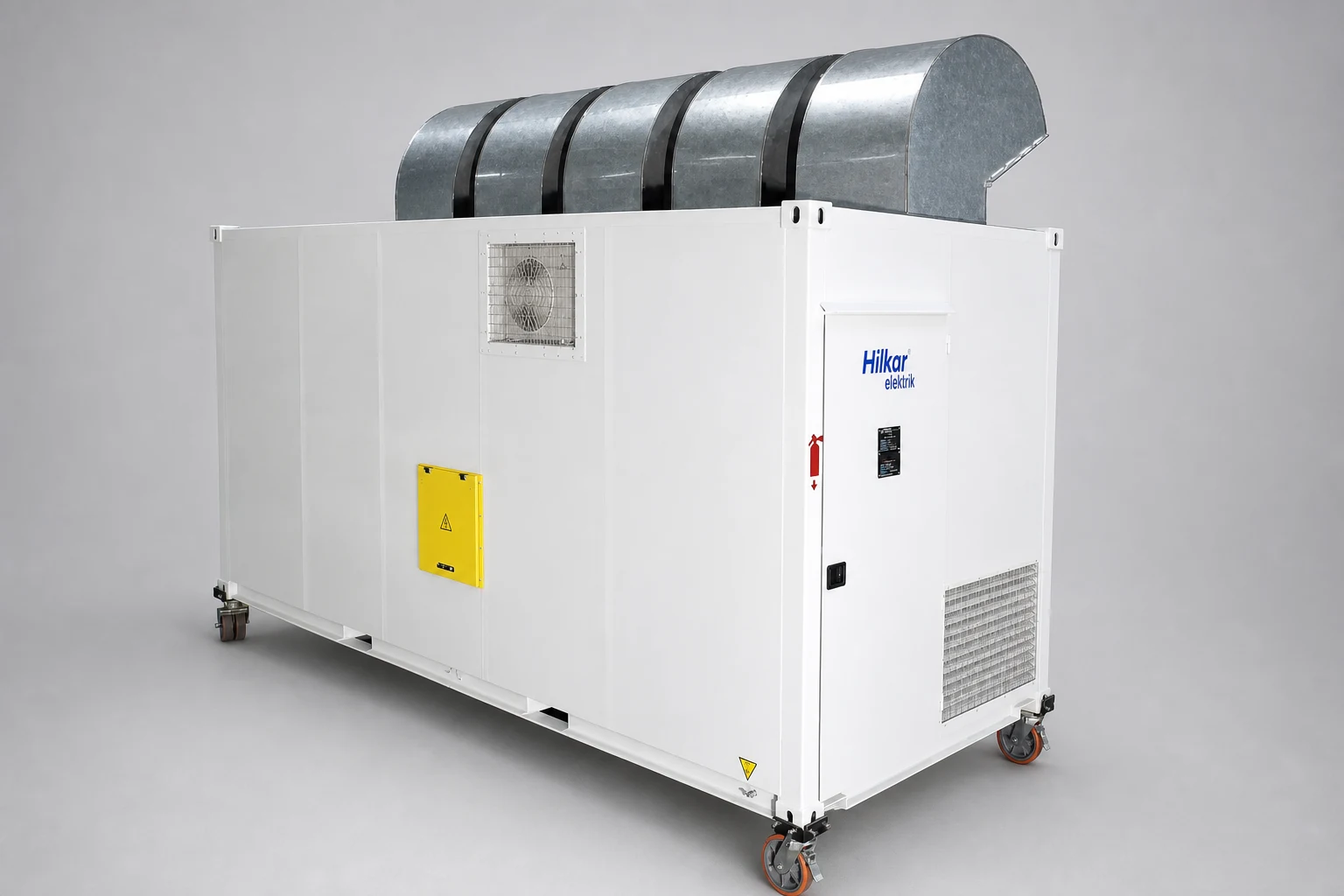
Hilkar designs and manufactures customized load banks for testing diesel-electric locomotives. A diesel-electric powertrain consists of a high-power diesel engine, alternator, and rectifier system. Testing units are typically connected to the DC link of the powertrain to verify the performance of these components before locomotive commissioning.
Hilkar provides customized electrical and mechanical designs according to the testing requirements. The thermal design of these units allows the safe dissipation of both continuous rated power and short-duration peak power generated during locomotive testing.
Features of Locomotive Testing Units
- Customizable mechanical design and enclosure configuration
- Capability to dissipate power levels up to several megawatts
- Flexible control and monitoring options
- Minimal resistance variation over the operating temperature range
Trackside Resistors
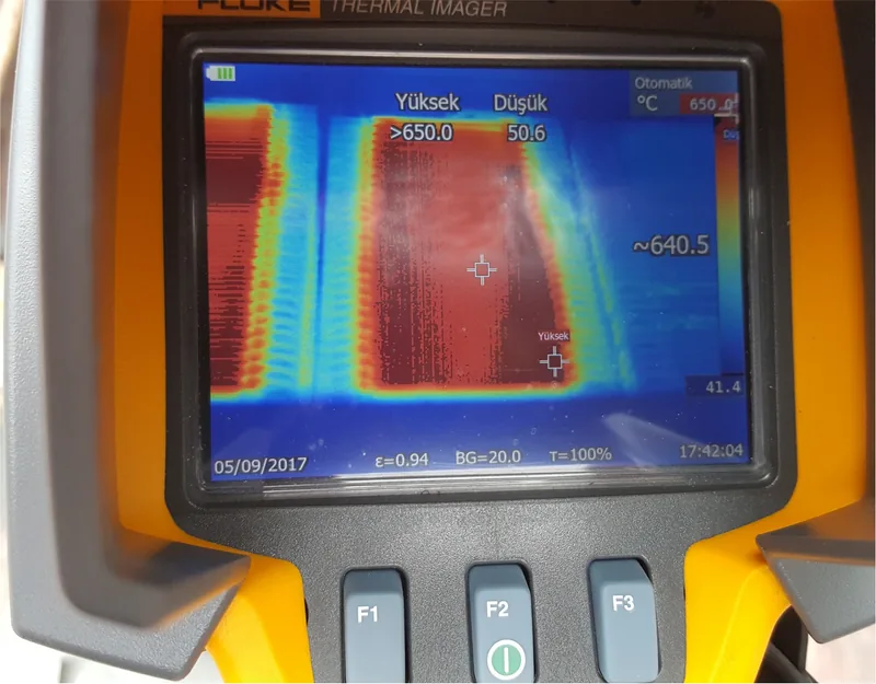
Trackside resistor units are used in metro and tramway DC traction networks to limit excessive catenary voltages. The EN 50163 standard defines the voltage characteristics and allowable limits for railway traction power supplies.
Many 750 VDC and 1500 VDC catenary systems use diode-based substations, where the DC voltage cannot be actively controlled. During regenerative braking or abnormal operating conditions, excess energy can increase the catenary voltage. Trackside resistors dissipate this excess energy and maintain the traction voltage within safe operating limits.
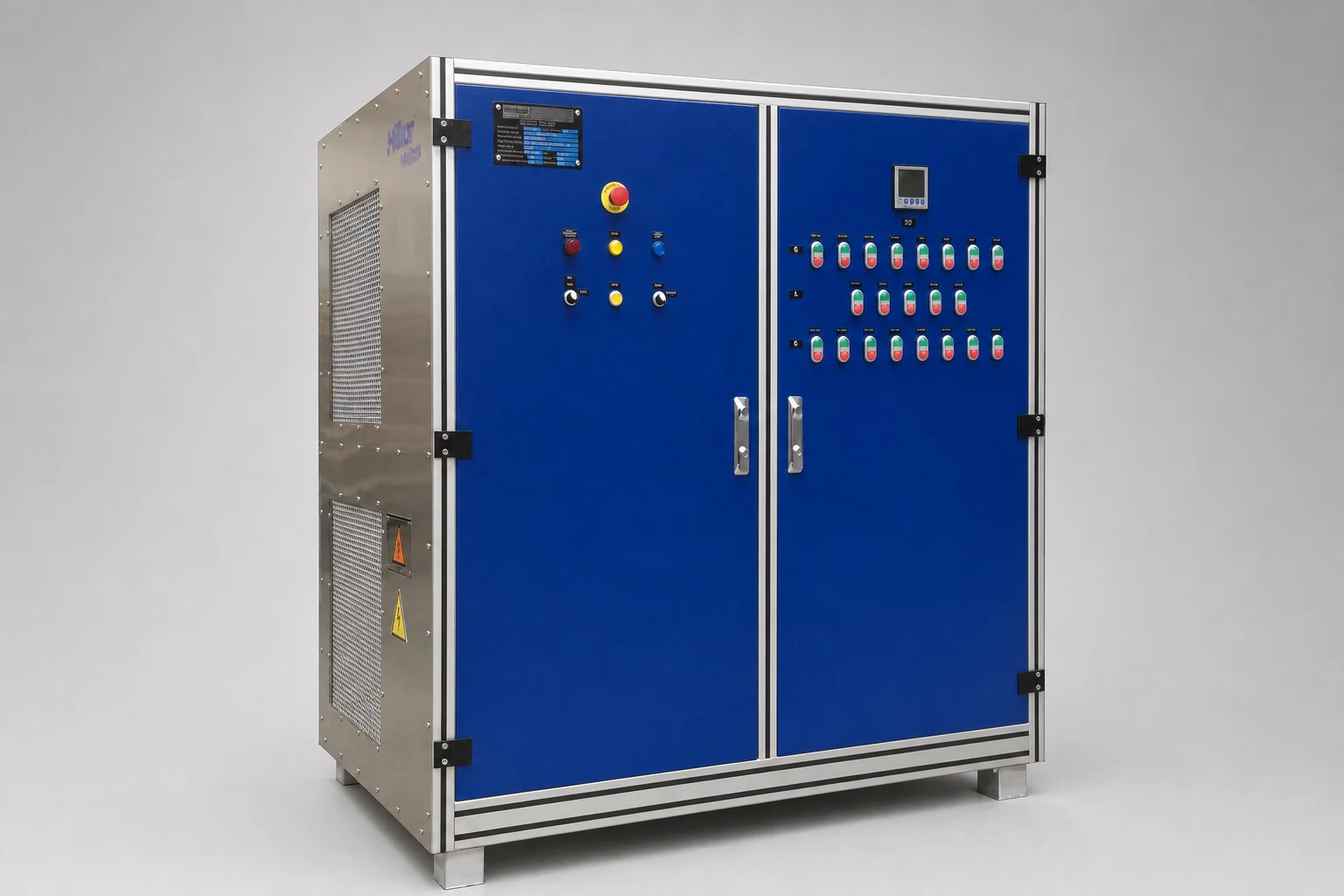
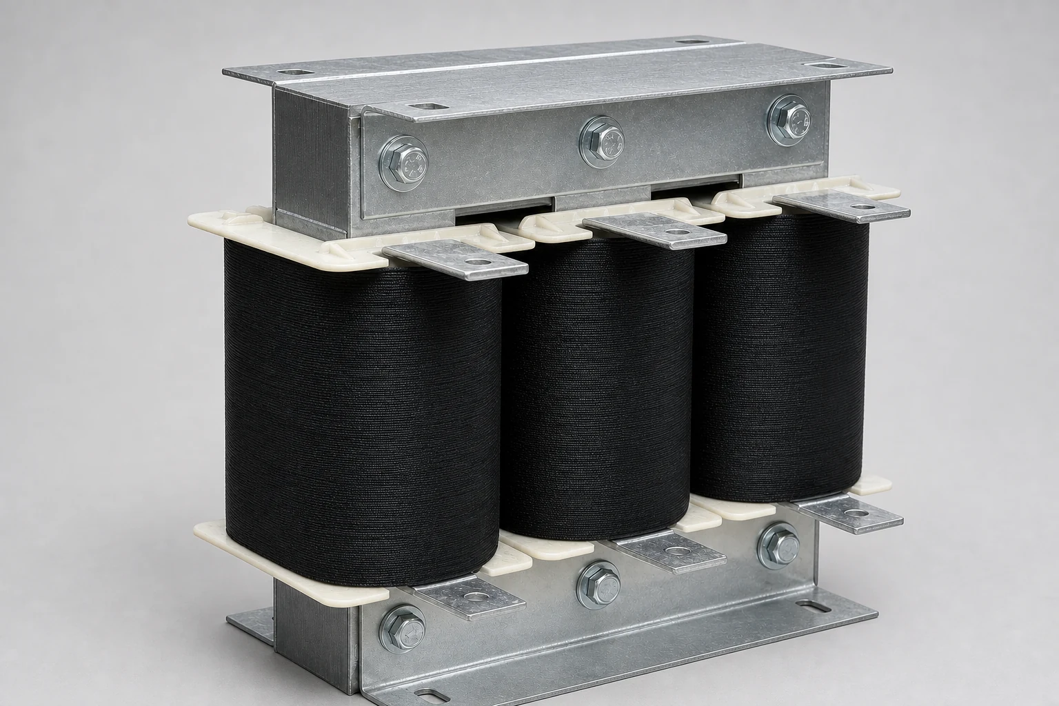
Inductive components are essential elements in both auxiliary converter systems and main traction power electronics. On-board AC and DC traction systems require inductive components with robust mechanical construction to withstand shock and vibration, along with optimized thermal designs for compact and reliable operation.
Air-Core / Iron-Core Chokes and Reactors
Line chokes are used to reduce harmonic currents generated by traction converters and to improve power quality in railway catenary systems. Air-core reactors provide stable inductance during high-current and short-circuit conditions, ensuring consistent filtering performance.
Hilkar designs custom sine filter inductive components for traction inverters to provide low-harmonic sinusoidal voltage waveforms for traction motors.
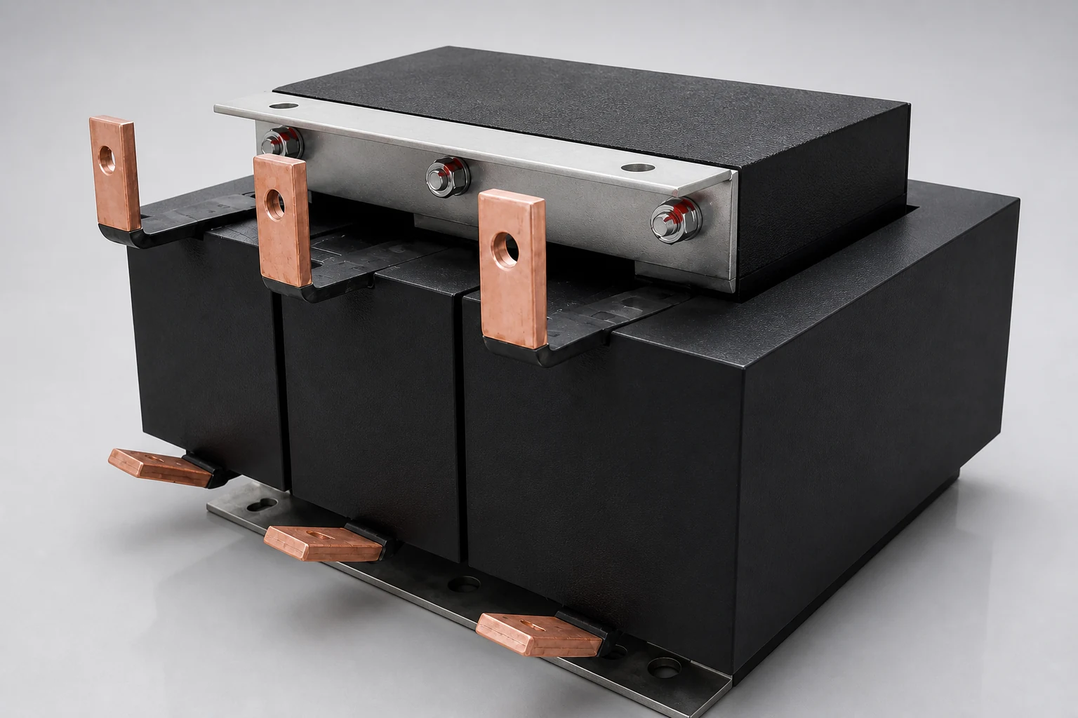
Transformers for Auxiliary Converters
Auxiliary converter transformers supply power to onboard auxiliary systems, control circuits, and electronic equipment. These transformers are designed for compact installation, high thermal performance, and reliable continuous operation under railway service conditions.
Standards
EN 61373 — Railway applications: Shock and vibration tests for rolling stock equipment IEC 60310 — Railway applications: Traction transformers and inductive components
Fire Protection Standard EN 45545
Hilkar provides customized onboard railway equipment designed to comply with the EN 45545 fire and smoke protection standard. The product range includes air-core reactors, iron-core reactors, transformers, and other inductive components developed for railway applications.