Neutral Grounding Resistors (NGRs), also known as Neutral Earthing Resistors (NERs), limit earth fault currents to protect electrical equipment and personnel in industrial and utility power systems.
Installed between the system neutral point and ground/earth, NGRs introduce resistance into the fault path to limit earth fault current to a predetermined safe level, reducing equipment stress and supporting reliable protection system operation.
- Limit single-phase earth fault currents to protect equipment in medium-voltage (MV) electrical networks
- Reduce transient overvoltages during earth faults while providing a measurable fault current to ensure reliable operation of earth fault protection relays
- Enhance protection for generators, transformers, and associated electrical equipment
- Reduce equipment damage, downtime, and maintenance costs
- Improve operational safety
- Provide a simple, reliable, and selective grounding protection method
- Enable the use of equipment and cables with lower insulation ratings compared with ungrounded (isolated neutral) systems
- Reduce step and touch voltages during earth fault conditions
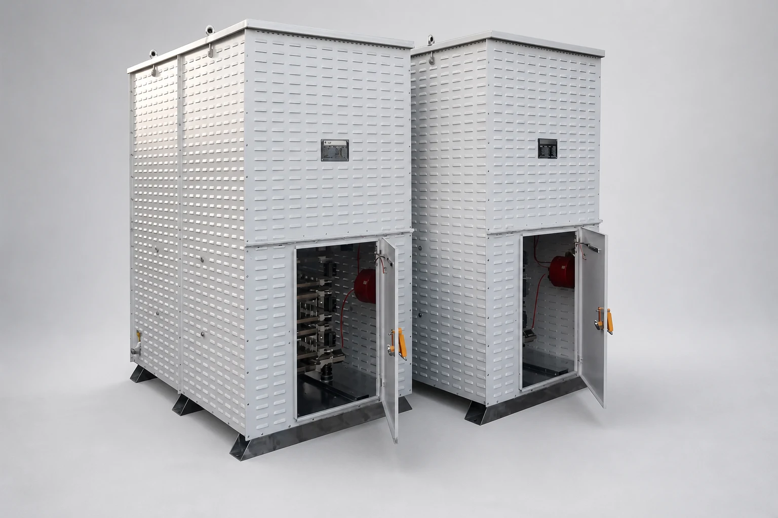
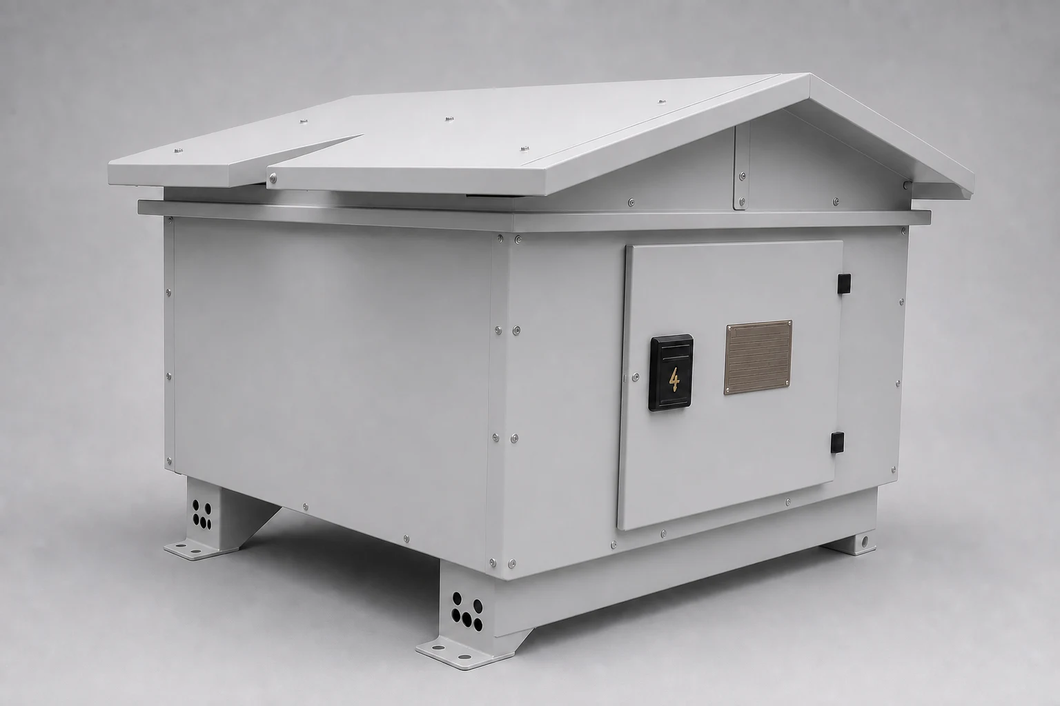
The earth fault current must be limited to a level that electrical equipment, such as generators and transformers, can safely withstand. At the same time, the current must remain sufficiently high to ensure reliable detection by earth fault protection relays. If the NGR resistance is too high, the resulting fault current may fall below the relay operating threshold, preventing proper fault detection.
In three-phase star-connected systems, phase-to-ground capacitances exist between the electrical network and earth. During an earth fault, these capacitances can contribute to transient overvoltages due to the redistribution of capacitive currents. The NGR must allow sufficient let-through current to control these effects and limit transient overvoltages.
NGRs are also classified according to their fault current withstand duration. Typical duty durations are 5–10 seconds, while extended-time NGRs are designed for critical applications such as petroleum, mining, and industrial power systems. In these applications, higher resistance values allow the resistor to withstand long-duration earth faults. When an earth fault occurs on one phase, the system generates an alarm while remaining in operation until a planned shutdown can be performed.
- CT
- Current transformer
- 51N
- Neutral overcurrent relay
- CT
- Current transformer
- 51N
- Neutral overcurrent relay
Hilkar NGRs (also known as NERs) are designed to absorb high levels of fault energy while maintaining temperatures within the limits specified by IEEE C57.32-2015. They are suitable for both indoor and outdoor installations across industrial and utility power systems.
The neutral connection is provided through a porcelain bushing or a high-voltage (XLPE) cable entry, available from the bottom, top, or side of the enclosure according to project requirements. Typical minimum cable cross-sections are 70 mm² for copper and 95 mm² for aluminium conductors. The most commonly specified enclosure protection rating is IP23, allowing effective cooling of the resistor elements.
Manufactured using stainless steel resistor elements, Hilkar NGRs provide excellent corrosion resistance and reliable operation in harsh environments, including coastal and desert locations. Each NGR is supplied with installation and maintenance documentation, including recommended protection relay settings where applicable. Hilkar provides complete technical support to ensure compliance with customer specifications and site conditions.
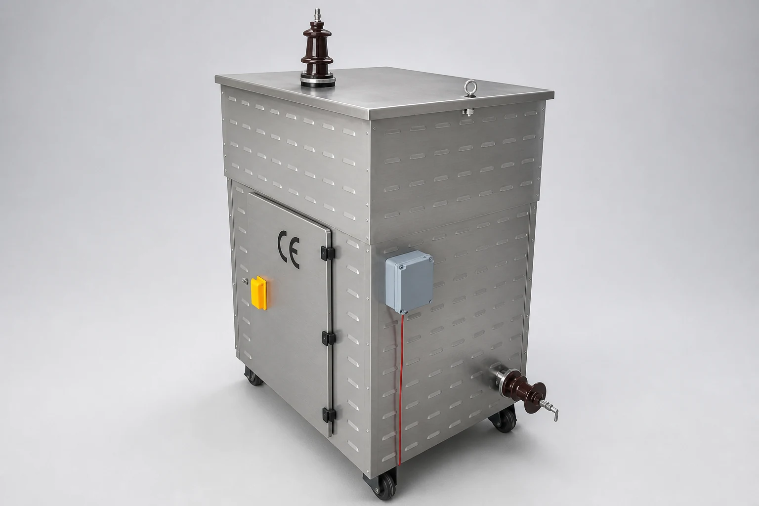
- Stainless-steel resistor elements
- Current transformers included (EN 61869-2 compliant)
- Bolted resistor element connections instead of welded joints, enabling quick on-site replacement and assembly of spare parts
- Hot-dip galvanized steel enclosure (painted or stainless-steel enclosures available upon request)
- Stainless-steel lifting eyebolts
- Impact-resistant construction (IK10)
- Solid top cover with a sloped design to prevent water accumulation
- Corrosion-resistant stainless-steel nameplate
- Explosion-proof (ATEX) options available upon request
- Operating Voltage
≤110kV
Line-to-line system voltage
- Rated Current
≤5000A
- Ambient Temperature
≤55°C
Consult Hilkar for higher ambient temperatures
- Resistor Material
Stainless steel
CrNi or CrAl
- Protection Degree
IP23
Indoor and outdoor applications; other protection degrees available upon request
- Standards
- IEEE C57.32-2015IEC 60076-25:2023IEC 60137 & 60273EN ISO 1461EN 10346EN ISO 12944IEC 60071IEC 60060IEC 60529
Routine Tests
- Insulation resistance measurement between enclosure and resistor elements
- DC resistance measurement
- Insulation test of resistor blocks
- Galvanization and/or paint thickness measurement
Type Tests
- Temperature-rise test
- Protection degree (IP) test
- Impulse voltage test (1.2/50 µs)
Special Tests (upon request)
- AC resistance measurement
- Seismic (Earthquake) Test
- Insulation resistance test (Megger)
- Elevated support stands for ground clearance and safety
- Units designed for hazardous and extreme locations (Ex-proof, ATEX certified)
- Stainless steel or aluminium enclosures on request
- Installation of voltage transformers
- Installation of protection relays
- Porcelain entrance bushings mounted on the top or side of the enclosure
- Grounding transformer installation
- Motorized or manual single-pole disconnector switches, load break switches, vacuum contactors, circuit breakers, surge arresters, and heaters inside the Neutral Grounding Resistors
- System Voltage (kV)
- Line-to-Neutral Voltage (kV)
- Rated Current (A)
- Resistance Value (Ω)
- Maximum ON Time (seconds) and Duty Cycle
- Bushing or Cable Entry Configuration
- Current Transformer Ratings (if applicable)
- Isolation and Switching Device (if applicable): Disconnector switch, load break switch, vacuum contactor, or vacuum circuit breaker.
- Special Options (if applicable)