Service continuity, personnel safety, and equipment protection are critical in 230–5000 V industrial power systems. High-Resistance Grounding (HRG) systems provide a safe, reliable, and cost-effective grounding solution for these networks.
HRG systems limit earth fault current by connecting a High-resistance Neutral Grounding Resistor (HNGR) between the neutral point of a transformer or generator and earth. In ungrounded delta-connected systems, where earth faults are difficult to detect and locate, an artificial neutral point is created using a grounding transformer. This enables a controlled earth fault current to flow, allowing reliable fault detection and location.
By grounding the neutral point through a high resistance, the system can continue operating during a single line-to-ground fault while minimizing equipment damage and transient overvoltages. The fault current is typically limited to 2–10 A, providing sufficient current for earth fault protection and fault location without requiring an immediate system shutdown
Approximate phase-to-earth fault currents in 230–5000 V power systems:
- Solidly Grounded Systems: 1000–6000 A
- Low-Resistance Grounded (LRG) Systems: 100–1000 A
- High-Resistance Grounded (HRG) Systems: 2–10 A
- Ungrounded (Delta) Cable Systems: 0.3–2.8 A/km (capacitive charging current)
Ungrounded systems: There is no intentional earth-fault current. The only current that flows during a single line-to-ground fault is the system capacitive charging current, which is often expressed as A/km of cable, not as a fixed 2–10 A.
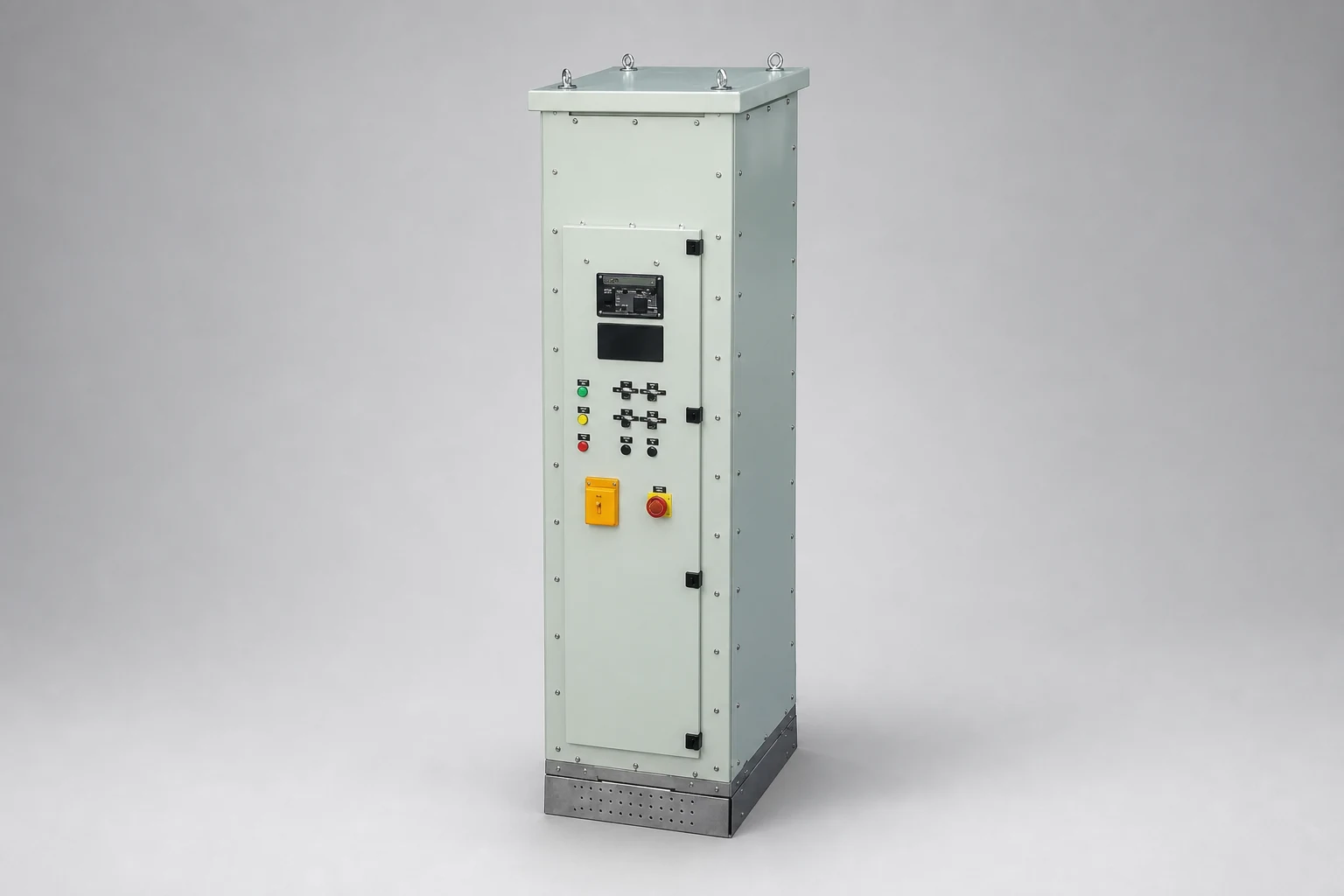
- 0–10 A analog ammeter and 0–250 V analog voltmeter mounted on the front panel
- Automatic power isolation via door interlock switch
- Test push button for fault indication verification
- Green indicator lamp for normal operating conditions
- Red indicator lamp and intermittent audible alarm during ground faults
- Pulse/Normal selector switch to increase fault current and generate an intermittent pulse for easier fault location
- Auxiliary volt-free contacts for pulse and alarm indications during ground faults.
- Standard enclosure dimensions (L × W × H): 600 × 600 × 1800 mm (other enclosure types and dimensions available upon request)
- Suitable for 230–5000 V three-phase power systems
- Optional data logging
When locating a phase-to-ground fault, the HRG system generates 10 A intermittent pulses (typically 1 second ON, 1 second OFF) superimposed on the normal 2 A fault current. These pulses make fault location faster and easier and are standard practice in modern HRG systems.
The pulse current is typically measured using a clamp-on ammeter. By tracing the phase cables with the clamp meter, the operator can identify the faulted feeder as the pulse current disappears beyond the fault location.
High-Resistance Grounding (HRG) systems provide an economical, reliable, and practical grounding solution for industrial power systems, particularly those operating at voltages up to 5 kV.
Because zero-sequence currents (3I0) flow through the neutral point due to cable line capacitance, the HRG alarm level is set higher than 3I0.
Star-connected system grounded through the HRG resistor
Delta-connected system grounded through a zigzag grounding transformer
Delta-connected system grounded through an open-delta grounding transformer
| Feature | High-Resistance Grounding (HRG) | Low-Resistance Grounding (LRG) | Solidly Grounded | Ungrounded |
|---|---|---|---|---|
| Supports line-to-neutral loads | - | - | ✔ | - |
| No feeder tripping during the first ground fault | ✔ | - | - | ✔ |
| Immunity to transient overvoltages | ✔ | ✔ | ✔ | - |
| Reduces arc-flash hazards | ✔ | - | - | ✔ |
| Easy first-fault location | ✔ | - | ✔ | - |
| Protects equipment against arc-fault damage | ✔ | - | - | - |
| System Voltage (V) | Cable Charging Current (240 mm²) 3I0 (A/km) | Motor Charging Current (A/1000 HP) | Damping Capacitor Current (A) |
|---|---|---|---|
| 240–1000 | 0.3 | 0.01 | — |
| 2400 | 1 | 0.1 | 0.78 |
| 4200 | 2 | 0.1 | 1.35 |
| 7200–12000 | 2.8 | 0.15 | 2.25 |