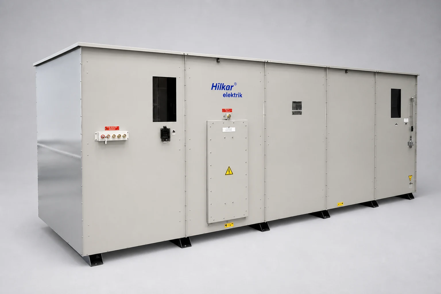
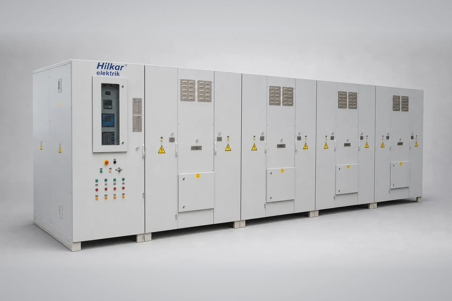
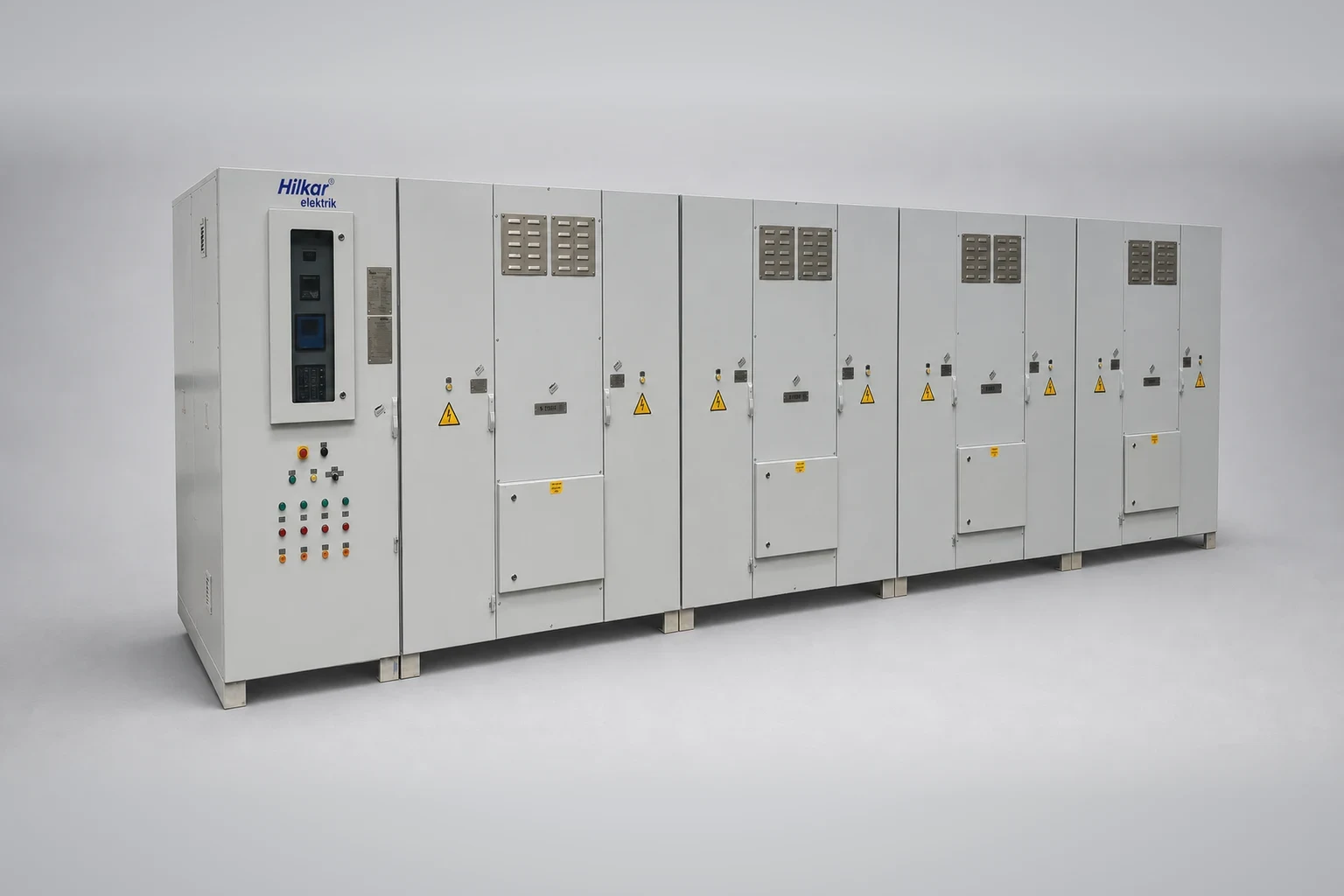
Hilkar Medium Voltage Capacitor Banks are complete, factory-assembled systems designed for reliable reactive power compensation and easy installation. Each system integrates capacitor units, harmonic filter reactors (when required), switching and protection equipment, and a dedicated control system. Their modular design enables flexible indoor or outdoor installation, providing efficient power factor correction and improved power quality for a wide range of medium-voltage applications.
Hilkar MV Capacitor Banks are complete, factory-assembled systems that include:
- Ready-to-install, stand-alone design
- Earthing switch for safe capacitor isolation and grounding
- Iron-core or air-core harmonic filter reactors, or air-core inrush current limiting reactors
- Optional low-inductance damping resistors for high-pass filters
- Vacuum contactors and capacitor fuses for reliable switching and protection
- Automatic Power Factor Correction (APFC) controller
- Overvoltage and overcurrent relays, current transformers (CTs), and voltage transformers (VTs)
- Touch-safe design
- Optional double-star configuration with unbalance protection
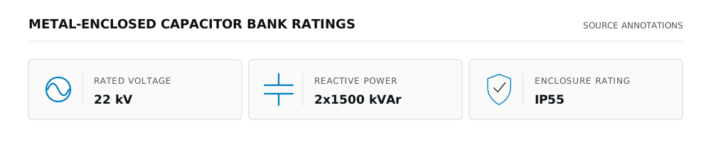
- Operating voltage from 2.4 kV to 36 kV, 50/60 Hz, up to 200 kV BIL
- Smoke detector for enhanced safety
- Modular design suitable for indoor or outdoor installation
- Power Factor Correction
- Harmonic Filtering
- Overvoltage Mitigation
- Reduction of System Losses
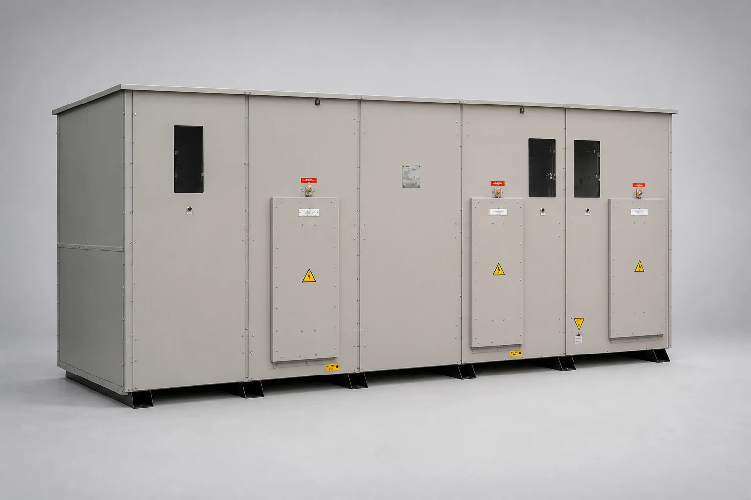
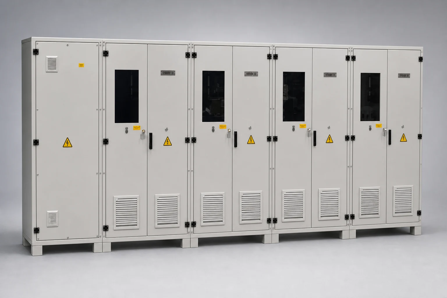
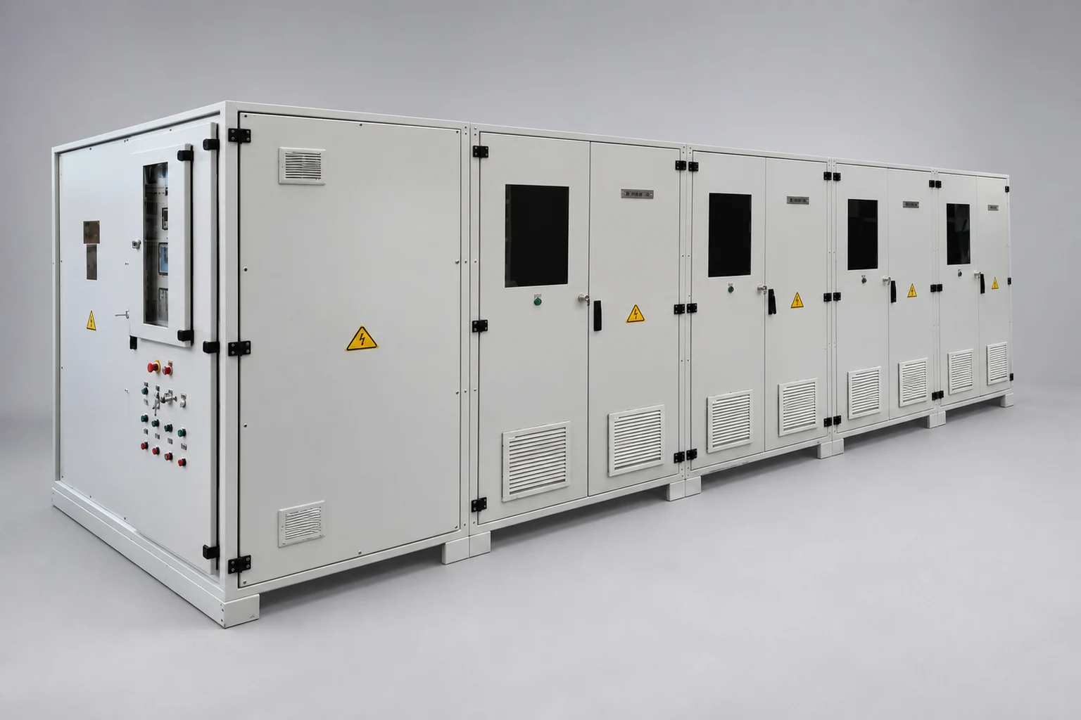
Hilkar MV Capacitor Banks are available in metal-enclosed or ISO containerized configurations to suit site requirements, installation conditions, and environmental applications.
Standards: IEEE Std. 1036, IEC 60871-1
- VCB
- Vacuum circuit breaker
- DS
- Disconnector with earthing switch
- CT
- Current transformer
- VT
- Voltage transformer
- 27
- Undervoltage relay
- 59
- Overvoltage relay
- 50/51
- Overcurrent relay
- 50N
- Neutral current relay (unbalance)
- VC
- Vacuum contactor
- F
- Fuse
- L
- Inrush current limiting (or harmonic filter) reactor
- Q
- Capacitor bank
- In
- Capacitor rated current
Select the protection fuse current as If ≅ 2 × In.
Set the ANSI 51 (time overcurrent) relay to 4–6 × In with a 0.1 s time delay for short-circuit protection.
Set the ANSI 50 (instantaneous overcurrent/overload) protection to 1.3 × In with a 4 s time delay.
Set the 50N relay (overload protection) with a 4-second delay at 0.05 × In.
Use the delta and star connection formulas to calculate the resistor R (kΩ) needed across the capacitor. This resistor drops the voltage of a capacitor bank with capacitance C (µF) below 75 V after 10 minutes (600 seconds).
Delta Connection
Star Connection
- R = Discharge resistor value (kΩ)
- C = Capacitance per phase (µF)
- U = System line-to-line voltage (V)
- In = Capacitor rated current (A) (used for protection settings, not in the resistor calculation)
- 75 V = Maximum residual voltage after 10 minutes (600 s) according to common capacitor discharge requirements.
The inrush current when energizing a capacitor bank depends on the system impedance and the capacitor bank characteristics. To prevent excessive switching currents, a current-limiting reactor may be connected in series with the capacitor bank.
Where:
- U = Phase-to-neutral voltage (V)
- Xc = Phase-to-neutral capacitive reactance (Ω)
- XL = Total inductive reactance between the capacitor connection points (Ω)
- Q, Q1, Q2 = Capacitor bank reactive power (kVAr)
- SSC = Short-circuit power at the capacitor connection point (kVA)
- IN = Rated capacitor bank current (Arms)
- ISC = Short-circuit current at the capacitor connection point (Arms)
To limit the capacitor switching inrush current to:
A current-limiting reactor should be connected in series with the capacitor bank. The reactor inductance is selected to reduce the peak inrush current while maintaining acceptable voltage drop and normal operating performance. This improves capacitor lifetime, minimizes contactor wear, and reduces electrical stress on switching devices.
symmetrical peak-current estimate
Example Calculation
Given:
- Capacitor bank rating, Q = 200 kVAr
- System voltage, U = 5 kV (line-to-line)
- Transformer apparent power, S = 1000 kVA
- Transformer impedance, ZSC = 5%
Step 1 – Calculate the capacitor rated current
IN = Q/(√3 × U) = 200/(√3 × 5) = 23 Arms
Step 2 – Calculate the short-circuit power
SSC = S/(ZSC/100) = 1000/(5/100) = 20,000 kVA
Step 3 – Calculate the capacitor bank inrush current
IC = IN√(2SSC/Q) = 23√((2 × 20,000)/200) = 23√200 = 325 A
Step 4 – Verify the inrush current limit
100 IN = 100 × 23 = 2300 A
Since:
IC = 325 A < 2300 A = 100 IN
Result:
The calculated inrush current is well below the recommended limit of 100 × IN. Therefore, an inrush current limiting reactor is not required for this application.
When an additional capacitor step is energized while n capacitor steps are already in operation, the resulting inrush current is calculated as follows.
Capacitor Step Current Relationship
Q (kVAr) = U (kV)² · C (µF) · ω · 10-3 = √3 · U (kV) · IN (A)
Where:
- Q = Capacitor step reactive power (kVAr)
- U = Grid line-to-line voltage (kV)
- C = Capacitance of the capacitor step (µF)
- ω = Angular frequency (rad/s)
- IN = Rated current of the capacitor step (A)
Initial Inrush Current Without Reactor
The peak inrush current when the (n+1)th capacitor step is energized is:
IC = √(2/3) · U · n/(n+1) · √(C/l)
Where:
- IC = Peak initial charging current (A)
- n = Number of energized capacitor steps before switching
- l = Inductance of busbars and cables between capacitor steps (µH/m)
Resonance Frequency
The natural resonance frequency of the capacitor switching circuit is:
fr = 1/(2π√(l · C))
Where:
- fr = Resonance frequency (Hz)
- l = Circuit inductance (H)
- C = Equivalent capacitance (F)
Inrush Reactor Calculation
To limit the peak inrush current to:
IC ≤ 100 IN
The required series inrush reactor is:
L (µH) = (2 × 10⁶)/3 × Q/(2πf) × (n/(n+1))² × 1/IC²
Where:
- L = Required inrush reactor inductance (µH)
- f = System frequency (Hz)
- Q = Capacitor step power (kVAr)
- IC = Allowed peak inrush current (A)
Inrush Current With Reactor
If a series inrush reactor with inductance L is installed, the expected peak inrush current becomes:
IC = √((2 × 10⁶)/3 × Q/(2πf) × (n/(n+1))² × 1/L)
This calculation is used to select the appropriate inrush current limiting reactor for medium-voltage capacitor banks with multiple parallel steps.
Example Calculation – Inrush Current for Parallel Capacitor Banks
Given:
- Busbar and cable inductance: l = 0.5 µH/m
- Distance between capacitor banks: 5 m
- System voltage: U = 5000 V (line-to-line)
- Number of energized steps before switching: n = 2
- New capacitor step: (n+1) = 3
- Capacitor step power: Q = 200 kVAr
- Frequency: f = 50 Hz
Step 1 – Calculate Capacitor Rated Current
IN = Q/(√3 × U)
IN = 200/(1.73 × 5) = 23 Arms
Step 2 – Calculate Capacitor Capacitance
C = √3(U × IN)/(U² × 2πf)
C = (1.73 × 5000 × 23)/(5000² × 2π × 50) = 25.3 µF
Step 3 – Calculate Inrush Current Without Reactor
IC = √(2/3) × U × n/(n+1) × √(C/l)
IC = 0.81 × 5000 × 2/3 × √(25.3/(0.5 × 5)) = 8589 Ap = 8.59 kAp
The allowable inrush current limit is: 100 IN = 100 × 23 = 2300 A
Since: IC = 8589 Ap > 2300 A
Result: A series inrush current limiting reactor is required.
Step 4 – Required Inrush Reactor Inductance
The minimum required reactor value is:
L (µH) ≥ (2 × 10⁶)/3 × (Q × 10-3)/ω × (n/(n+1))² × 1/IC²
ω = 2πf = 2π × 50 = 314 rad/s
L ≥ (2 × 106 × 0.2)/(3 × 314) × (2/3)² × 1/2300² = 35.66 µH
The minimum required reactor inductance is: L ≥ 35.66 µH
Step 5 – Check with a 50 µH Reactor
If a 50 µH inrush reactor is installed:
IC = √(2/3) × 5000 × 2/3 × √(25.3/50) = 1935 Ap
Comparison: 1935 A < 2300 A
Result: The 50 µH reactor successfully limits the inrush current below 100 × IN.
Step 6 – Resonance Frequency with Reactor
fr = 1/(2π√(L × C))
fr = 1/(2π√(50 × 10-6 × 25.3 × 10-6)) = 4475 Hz
Final Results
| Parameter | Value |
|---|---|
| Capacitor step current (IN) | 23 Arms |
| Capacitance per step (C) | 25.3 µF |
| Initial inrush current (without reactor) | 8.59 kAp |
| Maximum allowed inrush current | 2.3 kAp |
| Reactor required | Yes |
| Minimum reactor inductance | 35.66 µH |
| Selected reactor | 50 µH |
| Final inrush current | 1.94 kAp |
| Resonance frequency | 4.48 kHz |
This confirms that the selected 50 µH inrush reactor provides adequate switching current limitation for the parallel MV capacitor bank.
For capacitors, Imax = 1.3 × In
- Vmax = 1.1 Vn — 12 hours / day
- Vmax = 1.2 Vn — 5 min
- Vmax = 1.3 Vn — 1 min
The required capacitor bank rating is determined based on the desired capacitive reactive power compensation and the system voltage.
Where:
- S = Transformer rated power supplying the capacitor bank (kVA)
- SSC = Short-circuit power of the transformer supplying the capacitor bank (kVA)
- ZSC = Transformer short-circuit impedance (%)
- Qs = Required capacitive reactive power compensation (kVAr)
- Us = System voltage (V)
- QN = Required rated capacitor bank power (kVAr)
Determination of Required Capacitor Power
To provide a capacitive power of Qs at system voltage Us, the capacitor bank rated power must be selected considering the actual operating voltage:
Where:
- UN = Rated voltage of the capacitor bank (V)
- Us = Actual system voltage (V)
Since capacitor reactive power varies with the square of the applied voltage:
A capacitor bank designed for a higher rated voltage will deliver lower reactive power when connected to a lower system voltage.
Transformer Short-Circuit Power
The transformer short-circuit power can be calculated from:
Where:
- SSC = Short-circuit power (kVA)
- S = Transformer rating (kVA)
- ZSC = Transformer impedance (%)
These values are used for capacitor bank resonance and harmonic assessment.
- 4Vn (DC) 10 sec. or 2Vn (AC) 10 sec. between terminals
- Dielectric dissipation factor (tan(δ)) measurement
- Capacitance measurement
- Leakage Current Test
- Coating Thickness Measurement
- Capacitance Measurement
- Power-Frequency Withstand Test
- Insulation Resistance Measurement
- Full-Capacity Load Test
- Additional tests available upon request. Please contact Hilkar
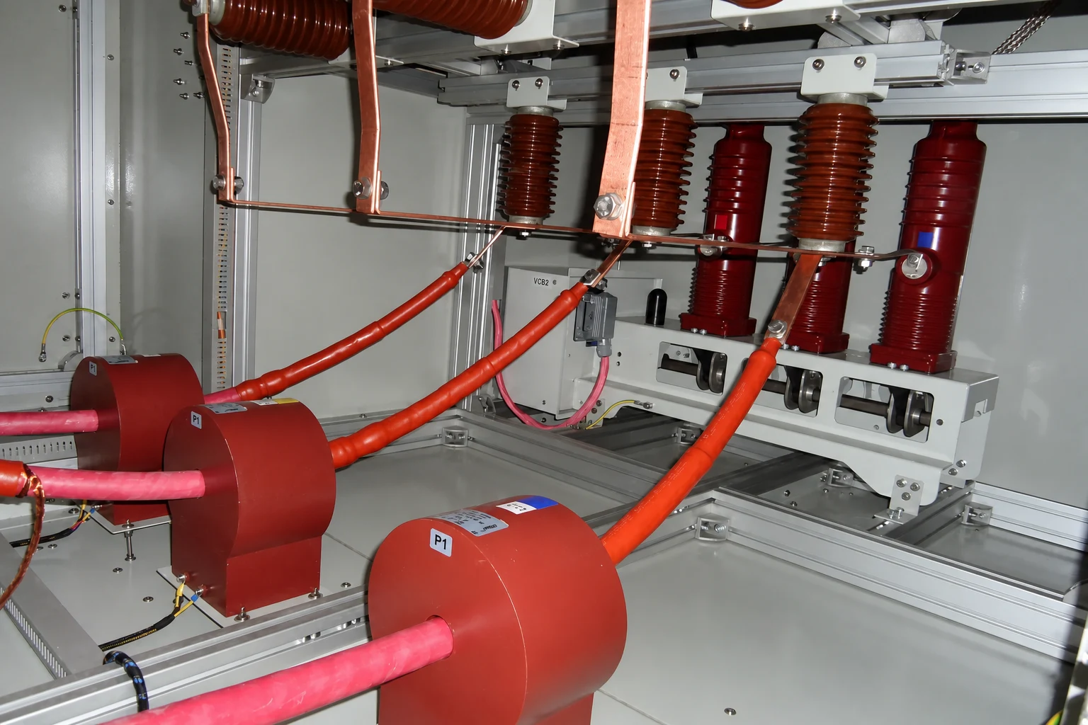
Vacuum circuit breaker at entry
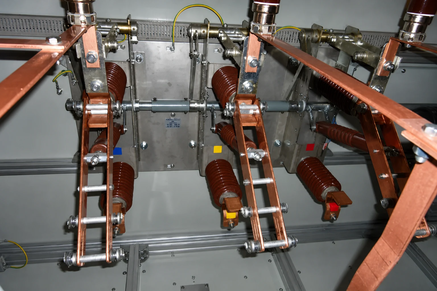
Disconnector switches for disconnecting and earthing the capacitors
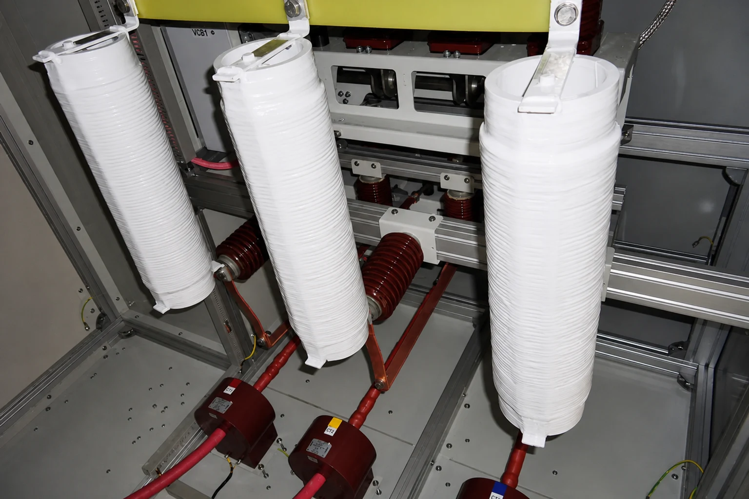
Equipped with inrush reactor
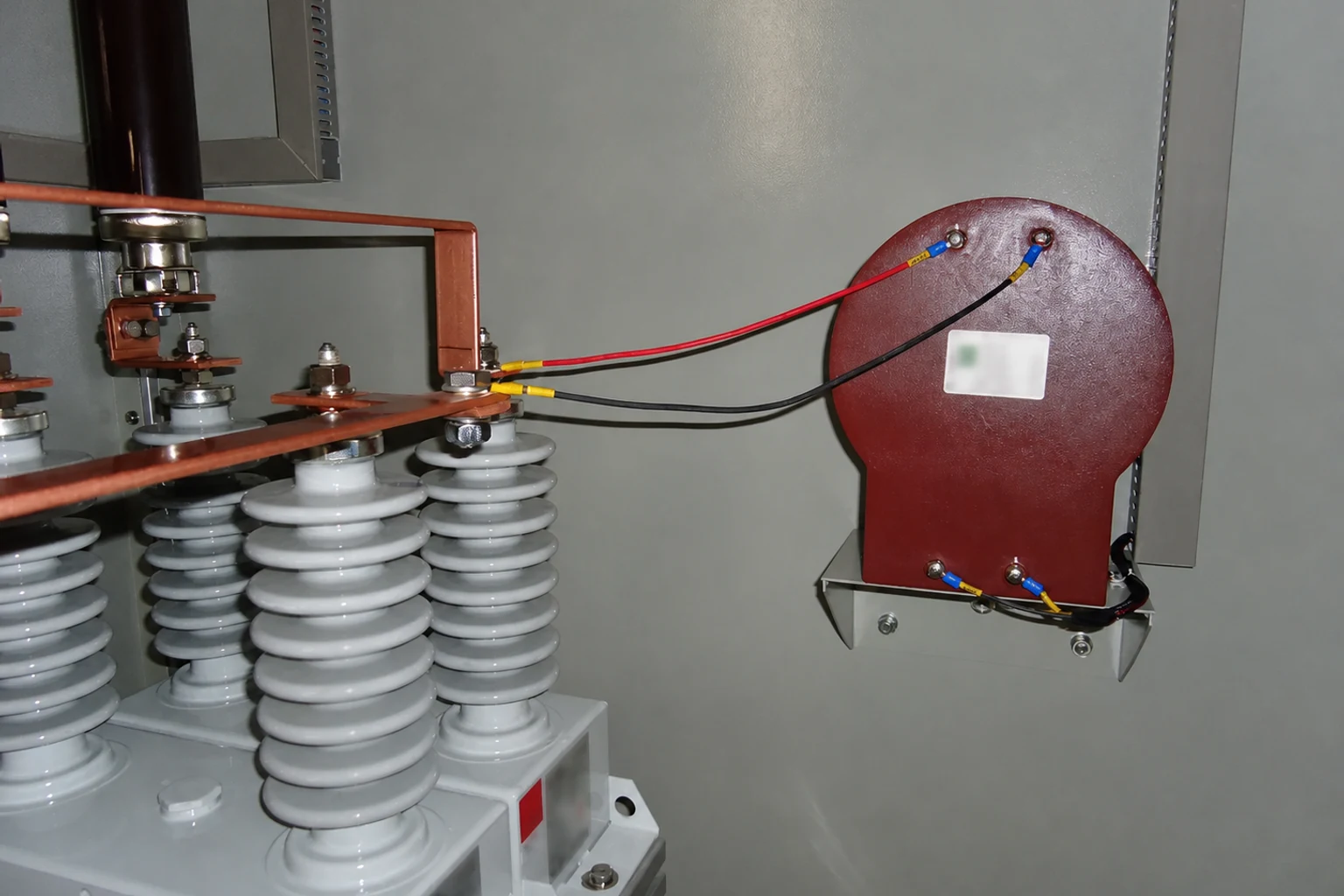
CT for unbalance protection
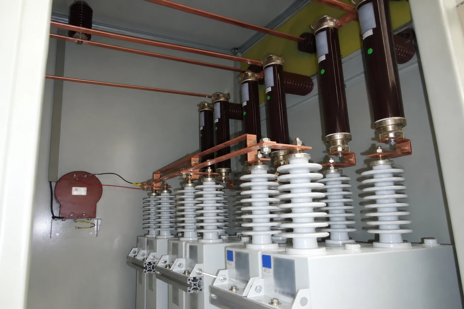
Capacitor protection fuses