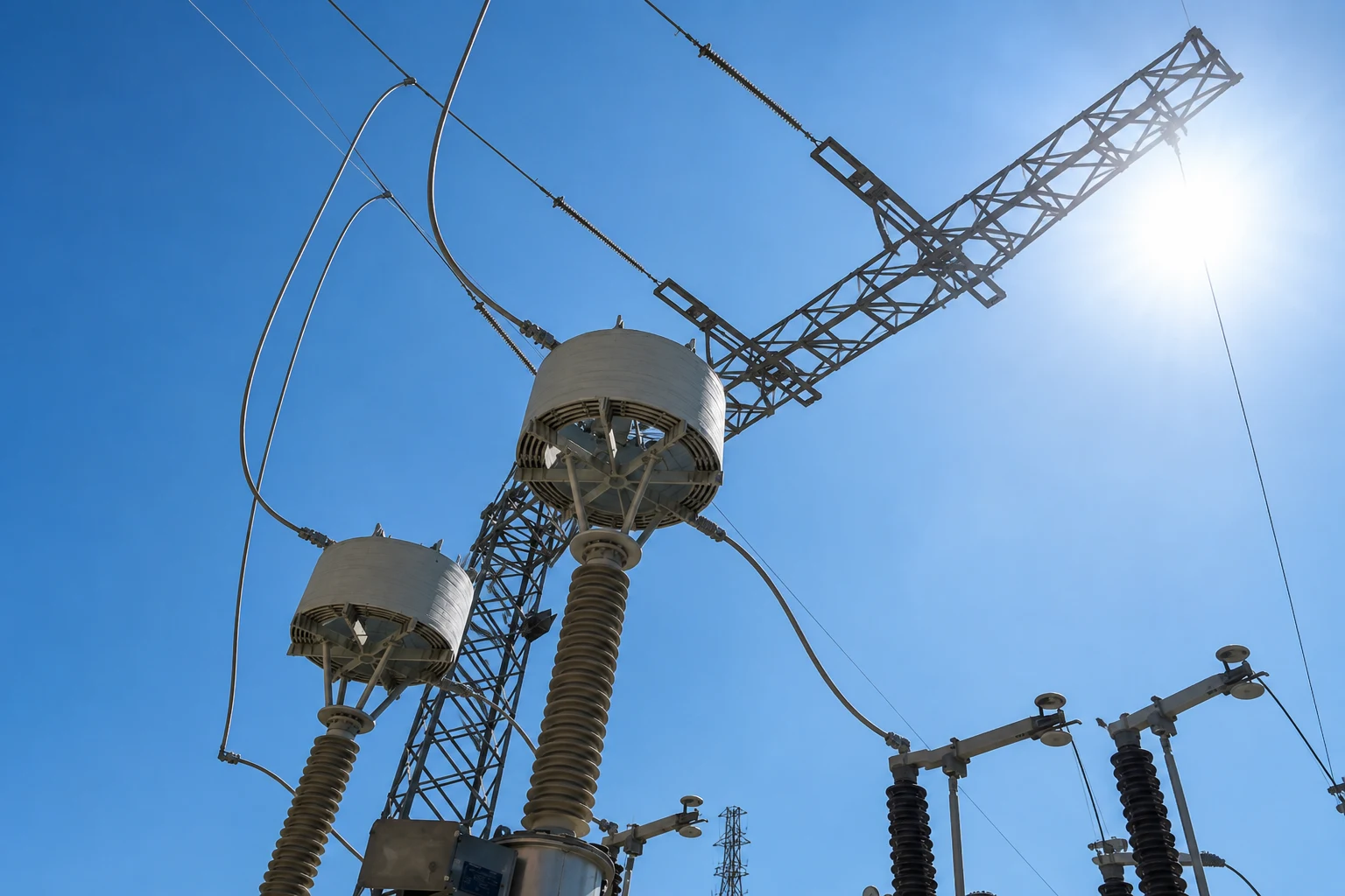
Line Traps are essential components of Power Line Carrier (PLC) communication systems used in high-voltage transmission and distribution networks. Installed in series with transmission lines, they block high-frequency carrier signals while allowing power-frequency current to pass with minimal impedance. Line Traps enable reliable teleprotection, voice communication, remote control, and supervisory monitoring between substations, ensuring secure and efficient operation of modern power systems. Their robust design provides dependable performance under continuous load and fault conditions.
- Designed and manufactured in accordance with IEC 60353, IEEE Std C93.4, and IEEE Std 643
- Engineered to meet specified short-circuit withstand requirements
- Lightweight design for easy transportation and installation
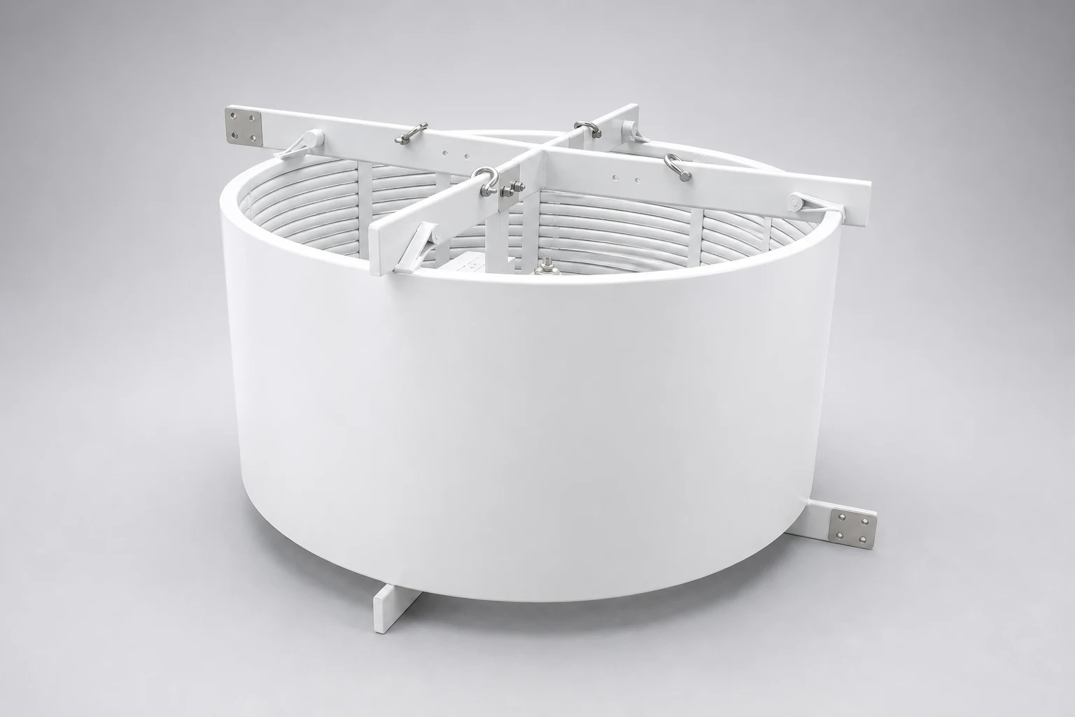
- Cooling spacers improve heat dissipation and reduce winding temperature
- Replaceable tuning unit for easy frequency adjustment without dismantling the coil
- Suitable for installation on capacitive voltage transformers (CVTs), support structures, insulators, or suspension mounts
- Low stray capacitance and high quality factor (Q) for superior PLC performance
- Corona grading spheres available for system voltages above 245 kV
- Compatible with a wide range of conductor terminal designs
- Available with DIN or NEMA terminal configurations
- Required inductance (mH)
- Rated current (A) at 50 Hz or 60 Hz
- Short-circuit current (kA) and fault duration
- Blocking frequency range (kHz)
- System voltage (kV)
- Required blocking impedance (Zb)
- Resistive component of blocking impedance (Rb)
- Mounting arrangement (CVT pedestal, support structure, or suspension type)
- Terminal configuration (DIN or NEMA)
- Bird barrier requirement (optional)
Standard Ratings
| Nominal Current (A) | Standard Short Circuit Currents (kA/1 second) | Inductance (mH) |
|---|---|---|
| 400 | 10–16 | 0.10 / 0.20 / 0.315 / 0.4 / 0.50 / 1.00 / 2.00 |
| 630 | 16–20 | |
| 800 | 20–25 | |
| 1000 | 25–31.5 | |
| 1250 | 31.5–40 | |
| 1600 | 40–50 | |
| 2000 | 50–63 |
- L1
- Main coil
- Zb
- Blocking impedance (Ω) of LT
- Rb
- Blocking resistance (Ω) of LT
- At
- Tapping loss
- Ab
- Blocking attenuation
- f′1, f′2
- Frequency limits of impedance blocking
- f1, f2
- Frequency limits of resistive blocking impedance
- fr
- Resonance frequency
- LA
- Surge arrester
- TD
- Tuning device
- Z1
- Network impedance (normally 400 Ω for bundled conductors and 600 Ω for single conductors)
- For line characteristic impedance ZL = 400 Ω (at bundled conductors)
- Blocking resistance Rb ≥ 570 Ω
- Tapping loss At ≤ 2.6 dB
| fr (kHz) | k |
|---|---|
| 20 | 0.75 |
| 40 | 0.80 |
| 60 | 0.85 |
| 80 | 0.88 |
| 100 | 0.90 |
15-minute overload capacity
| Ambient Temperature (°C) | × In |
|---|---|
| +40 | 1.4 |
| 0 | 1.5 |
| −40 | 1.6 |
In : Nominal Current (A)
Resistive component of blocking impedance
Minimum value of blocking impedance
Consult Hilkar for NEMA, DIN norms or others.
Standard pedestal fixation dimensions
For other pedestal fixation dimensions, consult Hilkar.