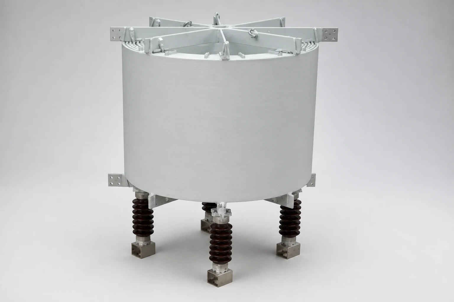
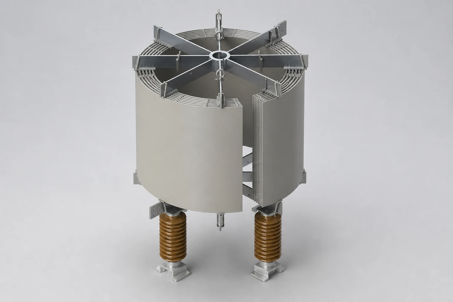
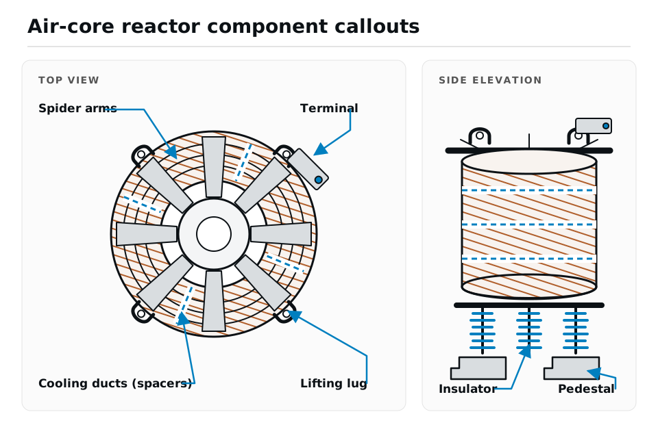
Line and Load Reactors are connected in series with the input and/or output of three-phase equipment such as variable frequency drives (VFDs), inverters, rectifiers, and UPS systems. They improve power quality and protect both the power system and connected equipment from the adverse effects of power electronic switching. Modern power electronic devices use semiconductor switches such as IGBTs, thyristors, and diodes, which generate harmonic currents, switching transients, and high dv/dt voltage spikes. Line and Load Reactors limit these effects by reducing harmonic distortion, suppressing current transients, and protecting equipment from voltage stress, ensuring reliable and efficient system operation.
Line and Load Reactors improve system reliability and equipment protection by providing the following benefits:
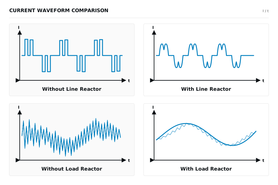
- Limits current transients in the connected circuit
- Reduces motor acoustic noise
- Minimizes motor heating
- Reduces harmonic distortion
- Minimizes motor heating
- Reduces the voltage rate of rise (dv/dt) and switching-induced voltage stress
- Simplifies fuse selection based on the motor rated current
Hilkar Line and Load Reactors are supplied with a standard 4% impedance (voltage drop). Other impedance values are available upon request to meet specific application requirements.
Hilkar custom-designs every Line and Load Reactor to provide an efficient and cost-effective solution for each application. Each design is optimized according to system voltage, current, inductance, application requirements, harmonic and interharmonic levels, installation constraints, switching transients, and target loss characteristics, ensuring reliable performance and long service life.
- Routine Tests (Inductance, Resistance, One-Minute AC Insulation Voltage Withstand Test, and Impulse Voltage Withstand Test)
- Short Circuit Withstand Test
- Temperature Rise Test
- Sound Level Test
- Seismic Test
- Designed and tested in accordance with applicable IEC and IEEE standards
- High quality factor (Q) for optimum performance
- High thermal capacity for continuous operation
- High mechanical strength to withstand severe short-circuit forces
- Fiberglass resin spacers for enhanced cooling efficiency
- Compact design with dimensions customized to project requirements
- Maintenance-free design for reliable long-term operation
- Flexible installation in side-by-side, delta, or vertical arrangements
- High-quality insulation varnish and corrosion-resistant surface coating
- Aluminium, hot-dip galvanized steel, or concrete support structures available upon request
- Elevated support stands available upon request
- Protective enclosures available upon request
- Rated Voltage
≤36kV*
- Type
Air core, dry type
- Altitude
≤1000m *
- Installation
Indoor / Outdoor
- Insulation Class
F
155 °C
- Winding Material
Aluminum or copper
- Insulation Material
Class F insulation film or epoxy-resin-reinforced fiberglass
- Ambient Temperature
−40 °C … 55 °C
- Cooling Method
AN
Air Natural
- Available Options
Taps with DIN or NEMA terminal configuration
*Consult Hilkar for higher ratings